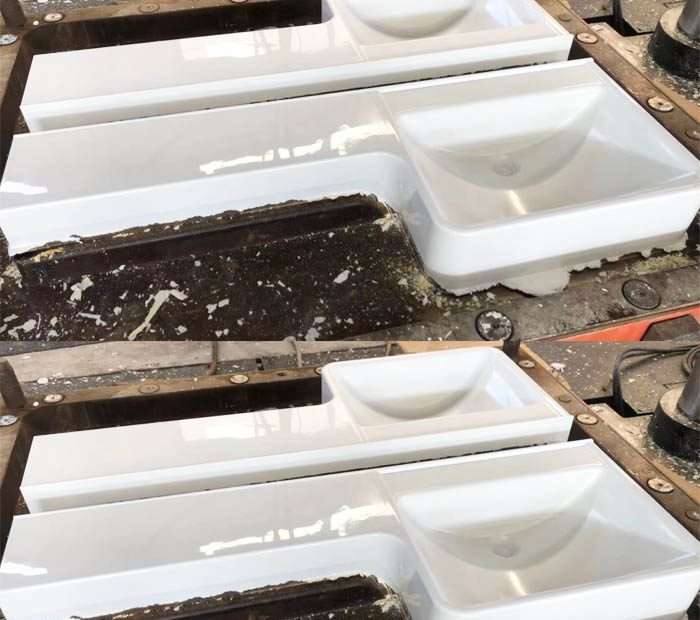
A tool shop in Dongguan cut steel on an SMC automotive bracket mold in 2023. Three weeks of CNC machining, $18,000 in steel and labor. First trial shot: the material didn’t fill the last 40mm of one rib. The part came out 15 grams light. They welded the mold, re-cut the gate, tried again. Third trial finally produced a good part. Total time from design freeze to first good shot: six weeks.
Across town, another shop ran the same bracket geometry through mold flow simulation before cutting any metal. The simulation showed the fill problem at the rib — in about 45 minutes of computation. The mold designer moved the gate 12mm and widened the rib entrance by 0.8mm in CAD. Tool cut once. First trial produced a good part on the second shot. Design freeze to sign-off: three and a half weeks.
That’s what simulation actually buys you. Not colorful images for a customer presentation. Two and a half weeks of schedule. One cutting of steel instead of two with welding in between. The math is straightforward, but most SMC mold shops still don’t simulate. Here’s how it works and why the shops that use it don’t go back.
What Is SMC Mold Flow Simulation — Material Science & Engineering Principles
SMC doesn’t flow like injection molding plastic. Injection molding simulation has been standard practice for thirty years — Moldex3D, Moldflow, Sigmasoft. You can train an engineer on it in a week. SMC flow is messier.
In injection molding, a single-phase melt flows through a runner system and fills the cavity as a continuous fluid front. The software tracks that front and predicts where it meets itself (knit lines), where it traps air, and where it freezes off early. Standard Navier-Stokes with viscosity models handles this. SMC is different: it’s a two-phase material — glass fibers suspended in a thermosetting resin paste — that enters the mold as a solid-like charge covering 50-70% of the projected area, then flows as the press closes. The fibers don’t just go along for the ride. They orient with the flow, they can break, they can mat together and stop flowing entirely if the resin races ahead of them. The resin is also curing while flowing, which means the viscosity is a moving target throughout the fill.
SMC flow simulation has to model:
- Bulk deformation with fiber suspension. The fiber-filled charge deforms under compression like a non-Newtonian fluid with a yield stress. Below a certain shear stress, it doesn’t flow at all — the fibers form a network that resists movement until the stress exceeds the network strength. This is called the Bingham fluid model with a fiber interaction term.
- Fiber orientation evolution. As the charge flows, fibers rotate. The final orientation at any point in the part determines local mechanical properties. The Folgar-Tucker model with orientation tensors tracks this — it’s computationally expensive (a 4th-order tensor per element) but necessary. Fiber orientation in the wrong direction can make a part 40% weaker in the load direction.
- Resin-fiber separation. If the flow velocity gets too high, the resin can outrun the fibers — the resin phase flows ahead, leaving a fiber-rich region behind near the charge center and a resin-rich region at the flow front. The flow front area ends up weak and brittle. Simulation can flag the velocity gradients that trigger separation.
- Cure kinetics coupled to flow. The resin is reacting (crosslinking) throughout the fill. As conversion increases, viscosity rises. The simulation couples a cure kinetics model (typically an Arrhenius-based Kamal-Sourour model) to the flow solver. If the resin cures too far before filling is complete, the part short-shots.
- Heat transfer from the mold. The 140-160°C mold heats the charge, lowering viscosity initially (helping flow) but accelerating cure (hindering flow). The thermal boundary at the mold wall is where cure starts first — the outermost resin skins over while the core resin still flows. This “skin-core” structure affects both fill behavior and final part properties.
“The first time I ran a simulation on a mold we’d already built — a parts tray with six deep ribs — the model showed exactly where the short shot was happening. Same location. Same geometry. I’d spent three days on the press floor solving that problem by trial and error. The simulation found it in an hour. I felt like an idiot, but I never cut another mold without simulating it first.” — Mold design engineer, Taizhou
Performance Data & Mechanical Properties
Simulation accuracy isn’t academic — it’s measured in trial reduction rate and correlation to physical parts. Here’s what the data says from shops that track simulation-to-reality correlation:
| Simulation Metric | Without Simulation | With Simulation | Improvement |
|---|---|---|---|
| Average mold trials before sign-off | 2.8 | 1.2 | 57% fewer |
| First-shot success rate (good part) | 25-30% | 70-80% | 2.7× higher |
| Tool rework events per mold | 2.1 | 0.6 | 71% fewer |
| Fill time prediction accuracy | N/A | ±8% vs physical | – |
| Knit-line location accuracy | N/A | ±5mm on a 500mm part | – |
| Fiber orientation (eigenvalue match) | N/A | 0.75-0.85 correlation | – |
| Average time: design freeze to sign-off | 5-8 weeks | 3-5 weeks | 35-45% faster |
The 0.75-0.85 fiber orientation correlation number needs context: it means the simulation correctly predicts the dominant fiber direction (within 15-25° of actual) at 75-85% of measurement points. This is good enough for structural prediction — knowing that fibers align with the flow direction lets you arrange the charge so the flow direction matches the load direction. A correlation below 0.6 means the simulation is missing something (usually the fiber-fiber interaction parameters, which need to be calibrated for each specific SMC formulation).
Manufacturing Process & Quality Control
Running an SMC flow simulation isn’t push-button. The inputs determine whether the output is useful or garbage. Here’s what actually matters in setting up a simulation.
Material characterization is the bottleneck. The simulation needs viscosity-as-a-function-of-shear-rate-and-temperature-and-cure for the specific SMC compound you’re molding. Generic SMC parameters from the software library will give you results, but they won’t match reality well enough to make mold-design decisions. You need either: your SMC supplier’s characterization data (some suppliers provide simulation-ready material cards), or your own testing — typically a parallel-plate rheometer to get the cure kinetics model parameters, plus compression testing at multiple temperatures and speeds to calibrate the flow model. Budget $5,000-8,000 and 2-3 weeks for material characterization if you’re doing it yourself for the first time. Subsequent formulations with the same resin system and similar fiber loading can reuse the model with minor recalibration.
Charge geometry input is more important than you’d think. The simulation needs to know the exact shape and placement of the SMC charge on the mold before the press closes. A charge that covers 65% of the projected area flows differently than one covering 55%. The charge thickness distribution matters too — a uniform-thickness charge flows differently from one that’s thicker in the middle. Measure the charge shape from the actual cutting pattern used on the shop floor, not the idealized rectangle from the CAD designer.
Mesh density trade-offs. A coarse mesh (5-8mm element size) runs in 20-40 minutes and catches major problems: gross short shots, large knit lines, obvious air traps. A fine mesh (2-3mm) catches subtle problems — thin knit lines at rib intersections, local fiber depletion around bosses, flow hesitation at thickness transitions — but runs in 2-4 hours. The practical workflow: coarse mesh during design iterations, fine mesh for the final review before releasing the tool design for manufacturing.
Vent placement comes from simulation. Air traps show up in the fill pattern as the last areas to fill. The simulation identifies these locations, and the mold designer places vents there. Without simulation, vent locations are a guess — “put them at the far corners and hope.” With simulation, vents go exactly where the air ends up. The difference is parts without burn marks (trapped air compresses, heats, and burns the resin) and without porosity at the fill end.
Application Spectrum: Where SMC Flow Simulation Excels
Not every SMC part needs simulation. For a simple flat cover 300×300×3mm with no ribs and no thickness changes — the mold will fill fine from the center. The value of simulation scales with part complexity:
Parts with deep ribs and bosses. Ribs are where SMC flow goes wrong. The material has to turn 90° from the main flow plane into the rib cavity. If the rib entrance is too narrow relative to the rib depth, the flow front stalls at the rib entrance while the main flow continues past it — the rib fills late, from both sides, with a knit line down the middle. Simulation shows exactly which ribs are at risk and at what fill percentage they’ll become problematic.
Parts with significant thickness variation. SMC flows faster through thick sections than thin ones. A part that transitions from 6mm to 2mm in a local area will see the flow race through the thick path and leave the thin area underfilled. Simulation predicts the fill imbalance so the designer can either: add a flow leader (a temporary thick path) in the thin area, or reposition the charge to give the thin section a head start.
Parts with inserts or overmolded features. Metal inserts (threaded bosses, mounting brackets) placed in the mold before charging disrupt the flow. The SMC has to split around the insert and rejoin downstream — creating a guaranteed knit line. Simulation shows the flow pattern around the insert and identifies whether the knit line ends up in a load-bearing area (bad) or a non-structural area (fine). If it’s in a bad spot, the insert position can usually shift 5-10mm to move the knit line out of the load path.
Large parts (>500mm in any dimension). The bigger the part, the further the SMC has to flow, and the longer the flow path means more time for the resin to start curing mid-flow. Parts over 500mm often need multiple charges placed at different locations rather than one central charge. Simulation determines the optimal number, size, and placement of charges for multi-charge molding.
Limitations & When NOT to Trust Simulation Alone
Simulation is a tool, not an oracle. It gets things wrong in predictable ways:
Fiber breakage during flow is hard to model. Simulation tracks fiber orientation but not fiber length reduction. In reality, fibers break as they flow through narrow passages and around sharp corners. The fiber length in the final part can be 30-50% shorter than the starting fiber length, which reduces strength below what the simulation predicts (since it assumes constant fiber length). For structural parts where strength margins are tight (<20% above requirement), always validate with a physical trial.
Charge placement sensitivity is higher in reality. A simulation run with the charge exactly at (X=250, Y=180) might show perfect fill. But on the shop floor, the operator places the charge by hand to an accuracy of about ±15mm. Run the simulation with the charge offset by 15mm in each direction — if any offset causes a fill problem, that mold is sensitive to operator variability and needs either: wider process windows (charge size, press speed adjustments) or a charge placement guide/ fixture on the mold.
Surface appearance prediction is poor. Simulation can’t predict surface waviness, gloss variation, or fiber read-through. These are cosmetic issues that depend on local cure history, resin shrinkage, and pigment distribution — none of which current commercial simulation packages model well. For A-surface (visible) parts, a physical trial is still the only way to evaluate appearance.
Calibration degrades over production runs. The material characterization was done on fresh SMC from one batch. If your production SMC varies batch-to-batch in maturation (thickening) level, the flow behavior will drift relative to the simulation. Shops that simulate should re-characterize the material every 6-12 months, or whenever the SMC supplier changes formulation. A material card from two years ago is producing numbers that may bear no resemblance to current production.
Latest Industry Innovations & Research
SMC flow simulation isn’t standing still. Three developments are changing the practice:
Coupled structural simulation. Moldex3D and Ansys now integrate flow simulation output (fiber orientation tensor field) as input to structural FEA. Instead of assuming isotropic material properties, the structural model reads the local fiber orientation from the flow simulation and applies anisotropic stiffness. The result: stress predictions that are typically 15-25% more accurate than isotropic assumptions. For weight-critical automotive and aerospace parts, this accuracy means thinner walls and lighter parts with the same safety factor.
Machine learning for material characterization. A 2025 study from the University of Stuttgart demonstrated that an ML model trained on 200 SMC viscosity curves could predict a new SMC formulation’s flow behavior from just its composition (resin type, fiber percentage, filler type and loading, maturation time) with 90% accuracy. This cuts material characterization from 2-3 weeks of rheometer testing to a single data entry step. The model isn’t commercially available yet, but the research trajectory is clear.
Real-time simulation on the press. Engel and Dieffenbacher are both working on press-integrated simulation that takes actual press parameters (closing speed profile, actual mold temperature at multiple thermocouple points) and runs a fast simulation during the first few seconds of the cycle to predict fill completion. If the model says the current shot won’t fill — adjust the press speed or pressure in real time. This is production-floor stuff, not design-phase, but it closes the loop between simulation prediction and actual molding conditions.
Do I need simulation software for every SMC mold, or just the complex ones?
Simple parts (flat, no ribs, length under 300mm, uniform wall thickness) don’t need simulation — the mold will fill reliably with a central charge and standard press parameters. Parts with any of: ribs deeper than 3× wall thickness, thickness transitions exceeding 2:1, metal inserts, or overall dimensions over 500mm — simulation will catch something that would otherwise be a trial-and-error fix. The rule of thumb: if your mold costs more than $15,000, simulation costs less than one additional trial-and-rework cycle.
How much does SMC flow simulation software cost?
Commercial packages (Moldex3D, Ansys with the compression molding module) run $15,000-30,000/year for a single-seat license. Training is another $3,000-5,000 for a one-week course. If you’re doing fewer than 10 new molds per year, it’s cheaper to outsource simulation to a consulting firm — expect $1,500-3,000 per mold for a standard fill + fiber orientation analysis. If you’re doing 15+ molds per year, the software pays for itself in reduced trial costs.
What’s the learning curve for an experienced mold designer?
An injection mold designer with Moldflow experience can learn SMC compression molding simulation in 2-3 weeks. The concepts are similar; the material models and setup are different. Someone with no simulation experience at all needs 4-6 weeks and should plan on their first 3-5 simulations being reviewed by an experienced analyst before acting on the results.
Can simulation predict warpage in SMC parts?
Partially. Warpage in SMC comes from three sources: thermal contraction (predictable, simulation handles it well), cure shrinkage (roughly predictable, depends on resin chemistry), and fiber orientation-induced anisotropic shrinkage (predictable if fiber orientation is modeled accurately). The correlation between predicted and actual warpage is typically 60-75% — good enough to identify which features will warp, and in which direction, but not good enough to compensate tool dimensions directly. Expect to do one physical trial to measure actual warpage and adjust the mold, even with simulation.