
SMC (Sheet Molding Compound) compression molds are the precision tools at the heart of the SMC molding process. A compression mold transforms a flat sheet of fiber-reinforced thermoset compound into a complex, high-strength, dimensionally accurate finished part — in a single press cycle lasting 1 to 5 minutes. For molders and OEMs, the quality of the mold directly determines part quality, cycle time, tool life, and per-part cost. Understanding the engineering behind SMC compression molds is essential whether you are commissioning a new mold, optimizing an existing process, or evaluating tooling suppliers.
At TSTAR Mold, we design and manufacture SMC compression molds that deliver parts meeting the most demanding automotive, electrical, and structural specifications. This deep dive covers the mold engineering principles, material selection, design trade-offs, and common defect-prevention strategies that define a high-performance SMC compression mold.
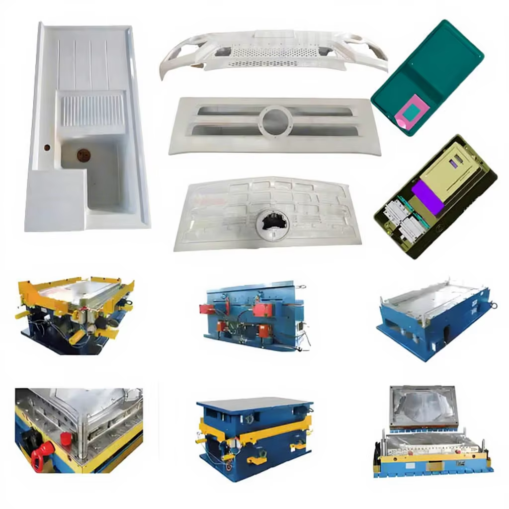
How SMC Compression Molding Works: The Mold’s Role in the Process
In compression molding, the mold performs three critical functions simultaneously: shaping, heating, and consolidating the SMC charge into the final part. The process begins when a pre-cut SMC charge (typically covering 50–70% of the mold cavity area) is placed into a preheated mold at 140–160°C. The press closes, applying 5–15 MPa of pressure. Under heat and pressure, the SMC viscosity drops dramatically, allowing it to flow and fill the cavity. The thermoset resin then crosslinks and cures, permanently locking in the part geometry.
The mold must manage material flow, trapped air evacuation, heat transfer uniformity, and dimensional control — all within seconds. A well-designed SMC compression mold achieves complete cavity fill without dry spots, knit lines, or porosity, while maintaining part thickness tolerances of ±0.05 mm or better across the entire surface.
Key Takeaway: An SMC compression mold is not just a cavity — it is a precision thermal management and material flow control system. Every design decision, from shear edge geometry to heating channel placement, directly impacts the quality and consistency of every part produced.
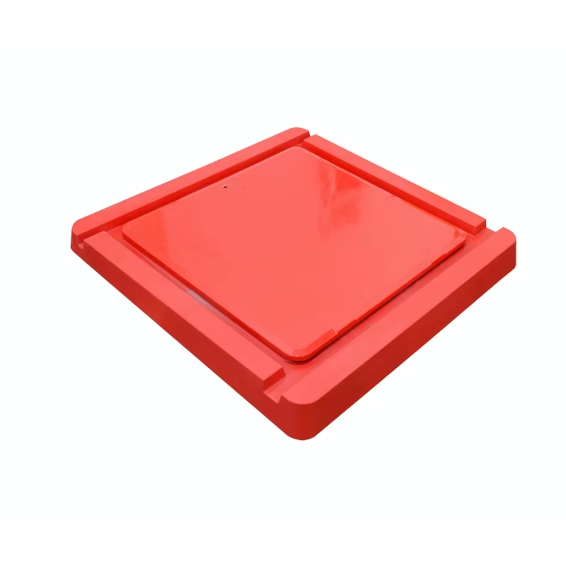
Key Components of an SMC Compression Mold
1. Cavity and Core
The cavity (female) and core (male) define the part geometry. SMC mold cavities are machined from pre-hardened tool steel (P20, 718H) or forged steel (Finkle, 2738) for high-volume production. The cavity surface finish directly transfers to the part surface: a Class A automotive exterior panel requires a SPI A-1 mirror finish on the mold cavity, achieved through progressively finer diamond polishing to Ra ≤ 0.025 μm. For structural parts where appearance is secondary, an SPI B-1 to B-3 finish (Ra 0.05–0.10 μm) is sufficient and more economical.
2. Shear Edge Design
The shear edge is the vertical interface between cavity and core that controls flash formation, part thickness, and demolding forces. Three common shear edge configurations are used in SMC molds: straight shear edge (simplest, for low- to medium-volume tooling), tapered shear edge with a 1–3° draft angle (reduces demolding force, extends tool life), and landed shear edge with a horizontal flash land (best flash control for high-volume production). The shear edge clearance is typically 0.03–0.08 mm per side, balancing flash minimization against the risk of steel-to-steel galling.
3. Heating System
SMC compression molds are heated using electric cartridge heaters, oil/steam channels, or induction heating. Electric cartridge heaters are most common for molds up to approximately 1 m², offering zoned temperature control with ±2°C uniformity. For large molds (>2 m²), oil or steam channels provide more uniform heat distribution at lower operating cost. The heating system must deliver sufficient thermal mass to rapidly reheat the mold surface after each cycle (typically 10–20 seconds recovery to within 3°C of setpoint). Inadequate heating or uneven temperature distribution is the root cause of under-cure, warpage, and part-to-part consistency problems.

4. Vacuum System (Optional but Recommended)
Vacuum-assisted compression molding evacuates air from the sealed cavity before and during mold closure. This eliminates air entrapment porosity, reduces cure time by 15–25%, and enables lower molding pressures (3–7 MPa vs. 8–15 MPa). A peripheral vacuum seal (typically silicone O-ring or lip seal) is integrated into the mold, connected to a vacuum pump capable of achieving ≤ 50 mbar absolute pressure within 5 seconds. For high-performance structural parts and Class A surfaces, vacuum assistance is increasingly becoming standard practice.
5. Ejection System
SMC parts are ejected using ejector pins, stripper plates, or a combination of both. Ejector pin placement must balance ejection force distribution against cosmetic requirements (pin marks are visible on the non-show surface). The ejection stroke is typically 15–30 mm beyond the deepest cavity point. For complex geometries with undercuts, hydraulic or pneumatic side cores are sequenced to retract before ejection — the mold design must integrate these mechanisms without compromising heating channel layout or structural rigidity.
Material Selection for SMC Mold Construction
The choice of mold material depends on production volume, part complexity, surface finish requirements, and budget. The table below is the industry reference for SMC mold material selection:
| Mold Material | Typical Hardness (HRC) | Production Volume | Relative Cost | Best For |
|---|---|---|---|---|
| P20 / 1.2311 Pre-hardened Steel | 28–32 | 50,000–200,000 cycles | $$ (moderate) | General-purpose production molds |
| 718H / 1.2738 Forged Steel | 32–36 | 200,000–500,000 cycles | $$$ (higher) | High-volume automotive, electrical |
| H13 / 1.2344 Hot Work Steel | 48–52 (heat treated) | 500,000+ cycles | $$$$ (highest) | Maximum durability, abrasive SMC formulations |
| Aluminum 7075-T6 | ~150 HB | 5,000–20,000 cycles | $ (lowest) | Prototypes, low-volume, quick heat-up |
| Stavax ESR / 1.2083 Stainless | 50–54 (heat treated) | 300,000+ cycles | $$$$ (highest) | Corrosion-resistant SMC formulations |
For corrosion-resistant applications — such as SMC formulations containing halogenated flame retardants that release trace acids during cure — Stavax ESR (electro-slag remelted) stainless tool steel or hard chrome plating (0.025–0.050 mm) on P20/718H is recommended to prevent pitting corrosion of the mold surface.
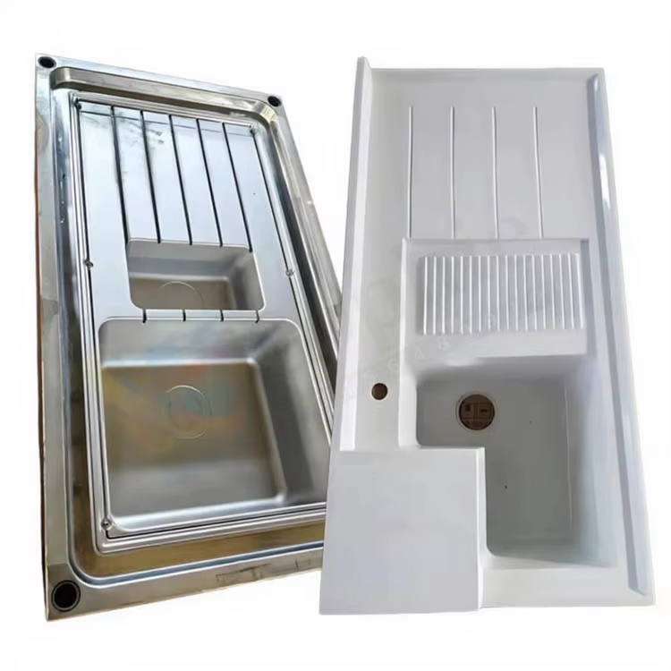
Design Considerations That Define Mold Performance
Shrinkage Allowance
SMC parts shrink during curing and cooling. The mold cavity must be machined oversize by the shrinkage factor: typically 0.05–0.15% for standard SMC, and 0.02–0.05% for low-profile (LP-SMC) formulations (per ASTM D955). Shrinkage varies with fiber orientation, filler content, and part thickness — ribs and bosses may shrink differently than flat walls. Mold designers compensate by applying differential shrinkage factors to different features based on flow analysis and empirical data.
Draft Angles
Draft angles on vertical surfaces facilitate part ejection. For SMC compression molds: minimum 1° draft on polished surfaces, 1.5–3° on textured surfaces, and 3–5° on deep ribs or bosses (per ISO 6751 / DIN 16756). Insufficient draft increases ejection force, stresses the part, and accelerates mold wear — it is the single most common cause of part sticking, surface scuffing, and premature ejector pin failure.
Venting
As the SMC flows and cures, trapped air and volatile byproducts must escape. Venting is provided by peripheral vents (0.03–0.05 mm deep), ejector pin clearances (0.01–0.02 mm radial), and vacuum ports (when vacuum assist is used). Inadequate venting causes burn marks, porosity, incomplete fill, and inconsistent cure. For large parts (>1 m²), peripheral vent channels spaced every 200–300 mm around the parting line perimeter are standard practice.
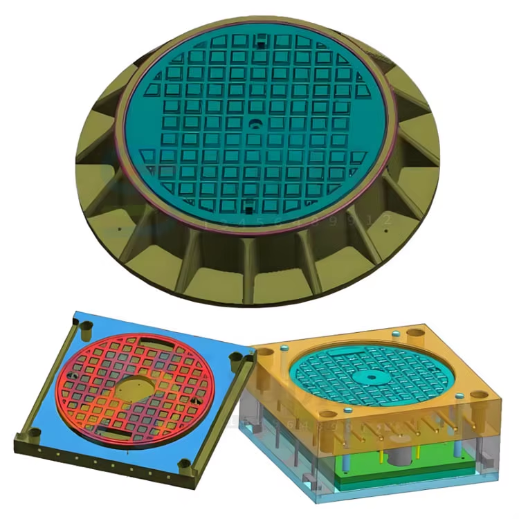
Common SMC Molding Defects and Mold Design Solutions
- Porosity / Voids. Caused by trapped air or volatiles. Mold solution: add vacuum assist, increase vent depth to 0.05 mm, or reposition charge pattern to alter flow front convergence.
- Warpage. Caused by non-uniform shrinkage due to temperature gradients or fiber orientation variation. Mold solution: improve heating channel uniformity (reduce ΔT across cavity to < 3°C), adjust gate/charge location to balance fiber flow, or apply differential cooling in hotter zones.
- Flash (Excessive). Caused by oversized shear edge clearance or mold deflection under pressure. Mold solution: tighten shear edge clearance to 0.03–0.05 mm, add backup support pillars to reduce platen deflection > 0.05 mm, or switch from straight to landed shear edge design.
- Surface Waviness / Orange Peel. Caused by resin-rich areas or insufficient mold surface polish. Mold solution: upgrade cavity polish to SPI A-2 or A-1 (Ra < 0.05 μm), verify that the SMC formulation's low-profile additive is compatible with the mold temperature profile.
- Sticking / Difficult Demolding. Caused by insufficient draft, mold surface adhesion, or overcure. Mold solution: increase draft angle to > 2°, apply semi-permanent mold release coating (e.g., Chemlease or similar), or reduce mold temperature near the cavity wall by 5–10°C to prevent premature cure at the surface.
- Knit Lines. Caused by flow fronts meeting and failing to fuse completely. Mold solution: reposition the charge to promote unidirectional flow, increase mold temperature by 5–10°C in the knit line region to extend flow time before cure, or increase press closing speed to reduce flow-front cooling.
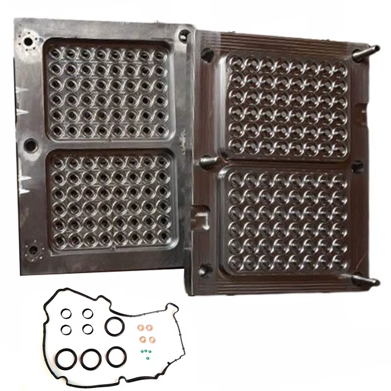
SMC Compression Mold Cost Breakdown
Understanding the cost structure of an SMC compression mold helps in budget planning and supplier evaluation. For a typical medium-sized SMC mold (cavity area ~0.5–1.0 m², P20 steel):
| Cost Component | Percentage of Total | Key Variables |
|---|---|---|
| Mold Design & Engineering | 15–20% | Complexity, simulation (CAE), DFM iterations |
| Steel Material | 10–15% | Grade (P20 vs 718H vs H13), block size |
| CNC Machining | 30–40% | Cavity complexity, number of electrodes needed for EDM |
| EDM (Sinker + Wire) | 5–15% | Deep ribs, sharp corners, textured surfaces |
| Polishing & Finishing | 5–10% | Surface finish spec (B-3 to A-1) |
| Heating System Integration | 5–8% | Cartridge heaters vs oil channels |
| Assembly, Tryout & Validation | 10–15% | First-article inspection, process window development |
The total mold cost typically ranges from $15,000–$50,000 for a standard production mold and $50,000–$150,000+ for a large, high-cavitation, Class A automotive mold. Mold lead time is 8–16 weeks depending on complexity and supplier capacity.
Frequently Asked Questions
What is the typical service life of an SMC compression mold?
A well-maintained SMC compression mold in P20 steel can produce 100,000–200,000 cycles before major refurbishment. With 718H forged steel, 200,000–500,000 cycles is achievable. Key factors affecting mold life include: SMC formulation (abrasive fillers accelerate wear), molding pressure (higher pressure increases shear edge wear), mold maintenance frequency (cleaning, reapplication of release agent, inspection of shear edges), and storage conditions (climate-controlled storage prevents corrosion). Hard chrome plating (0.025–0.050 mm) can extend mold life by 50–100% at a cost premium of 10–15% of the base mold price.
Can an SMC compression mold be converted to run a different part?
Partial conversion is possible but limited. Cavity inserts can be used to modify local geometry within an existing mold frame — cost-effective for part revisions or family mold configurations. However, a complete conversion to a different part shape generally requires a new cavity and core, which is 60–80% of a new mold’s cost. For this reason, it is often more economical to commission a new mold optimized for the new part geometry than to heavily modify an existing one. Exceptions: mold frames and heating systems can sometimes be reused if the new part has similar platen dimensions and thermal requirements.
What is the difference between a compression mold and an injection mold for thermoset composites?
The fundamental difference lies in how the material enters the cavity. In compression molding, the SMC charge is placed directly into the open mold cavity; the press closes and the material flows under compression. In injection molding of thermoset composites (BMC injection), the material is plasticized in a screw/barrel and injected through a sprue and runner system into a closed mold under high pressure (50–150 MPa). Compression molds handle longer fiber lengths (25–50 mm vs. 6–12 mm) and achieve better mechanical properties in the finished part, but injection molds offer faster cycle times for small, complex parts and can run fully automated without manual charge placement.
How do you maintain an SMC compression mold for maximum service life?
Essential maintenance practices: (1) Clean the mold cavity and shear edges after every production shift with a soft brass scraper and approved solvent — never use steel tools that can scratch the cavity surface. (2) Reapply semi-permanent mold release to the cavity surface every 50–100 cycles or per the release agent manufacturer’s recommendation. (3) Inspect shear edge clearance with feeler gauges every 1,000 cycles — recut or recondition if clearance exceeds 0.10 mm. (4) Verify heating system performance (temperature uniformity, heater continuity) monthly. (5) Store the mold in a dry, temperature-controlled environment (20–25°C, < 50% RH) with cavity surfaces protected by a light coat of rust-preventive oil. (6) Keep a mold cycle log — tracking cycles, maintenance events, and any quality issues enables predictive maintenance and identifies wear trends before they cause production downtime.
What surface finishes are achievable directly from an SMC compression mold?
With a properly polished mold cavity and an in-mold coating (IMC) or Class A SMC formulation, SPI A-1 to A-2 gloss levels are achievable directly from the mold, meeting automotive exterior paint-ready specifications without secondary sanding or priming. The limiting factors are the SMC formulation (Class A SMC with low-profile additives is required), the mold cavity polish quality (Ra ≤ 0.025 μm), and the molding process control (temperature uniformity ±2°C, consistent charge placement and press closing profile). For non-appearance parts, SPI B-1 to B-3 finishes are standard.
Soundbite: A high-performance SMC compression mold combines precision-machined P20 or 718H tool steel, optimized shear edge geometry (0.03–0.08 mm clearance), uniform heating (±2°C), and vacuum-assisted venting to transform a flat fiber-reinforced sheet into a complex, dimensionally accurate, Class A finish part in a single 1–5 minute press cycle.
At TSTAR Mold, we specialize in designing and manufacturing SMC compression molds for automotive, electrical, construction, and industrial applications. Our in-house engineering team provides complete tooling solutions — from mold flow simulation and design optimization through CNC machining, tryout, and production support. Contact us today to discuss your SMC compression mold requirements or to request a quotation for your next tooling project.
Standards & References
The following industry standards are referenced in this article: