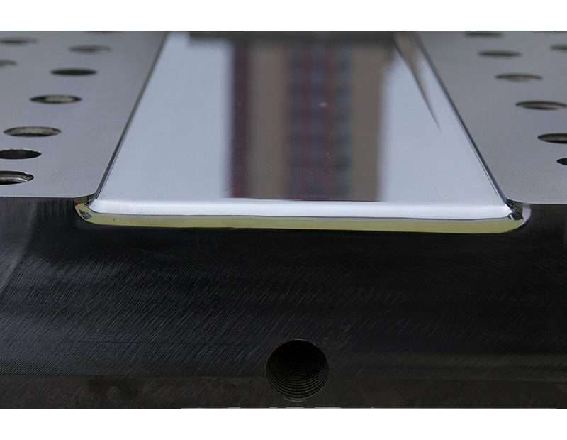
The pultrusion die is the heart of the pultrusion process — a precision-engineered tool that simultaneously shapes, compacts, and cures fiber-reinforced polymer profiles as they are pulled continuously through its heated cavity. A well-designed pultrusion die produces profiles with dimensional tolerance of ±0.1mm, fiber volume fractions above 60%, and surface finishes under 0.8μm Ra — while running 24/7 for months between refurbishments. A poorly designed die generates scrap, delamination, and catastrophic pull breaks that halt production.
This engineering guide covers the critical design parameters, material selection, thermal management, and maintenance practices that separate production-grade pultrusion dies from prototype failures.
Design Parameters & Performance Requirements
The pultrusion die cavity geometry must account for three distinct phenomena: thermal expansion of the die steel (the cavity grows by 0.1-0.3mm at operating temperature), resin shrinkage during cure (typically 5-8% volumetric for unsaturated polyester, 2-4% for epoxy), and the Poisson effect (the profile expands laterally when under axial pulling tension). The cavity dimensions at room temperature are calculated by back-calculating from the desired finished profile dimensions at ambient temperature, adding allowances for each effect.
The standard die cavity design uses three zones: the entrance zone (5-15% of total die length) has a tapered lead-in of 2-5° half-angle to gradually compact incoming wet fibers and squeeze out excess resin, the transition zone (10-20% of length) reduces the taper to 0.5-1° for progressive compaction, and the straight zone (65-85% of length) maintains the final profile cross-section while the resin cures. Total die length typically ranges from 600mm for simple small profiles (under 100mm² cross-section) to 1,500mm for large complex profiles (over 10,000mm²).
The pulling force required is a function of die length, profile perimeter, and the coefficient of friction between the curing composite and the die wall. A well-designed die with proper chrome plating and taper geometry operates at a pulling force of 2-5 kN for medium profiles; forces above 10 kN indicate excessive friction that will cause fiber breakage or surface defects. The gel point — where the resin transitions from liquid to solid — should occur at 40-55% of the total die length. Premature gelation (too early in the die) causes high pulling force and surface tearing; delayed gelation (too late) results in undercured profiles exiting the die.
Steel Selection: Properties Comparison Matrix
Pultrusion die steel must balance wear resistance, thermal conductivity, machinability, and cost across a tool that will process thousands of kilometers of abrasive glass and carbon fiber over its service life.
| Steel Grade | Hardness (HRC) | Thermal Conductivity (W/m·K) | Typical Die Life (km of profile) | Relative Cost |
|---|---|---|---|---|
| P20 (1.2311) | 28-32 | 34-38 | 50-150 (glass fiber) | 1.0x |
| H13 (1.2344) | 48-52 | 24-28 | 150-400 (glass fiber) | 2.0x |
| D2 (1.2379) | 58-62 | 20-24 | 300-800 (glass+carbon) | 3.0x |
| Stainless 420 | 50-54 | 24-28 | 200-500 (corrosion-resistant) | 2.5x |
| Carbide (WC-Co) | 88-92 HRA | 60-80 | 2,000+ (all fibers) | 10-15x |
P20 is the workhorse steel for glass fiber profiles at moderate volumes. H13 adds hot hardness and is preferred when processing high-temperature resins (epoxy, vinyl ester) at die temperatures above 180°C. D2 provides the highest wear resistance among tool steels and is specified for carbon fiber pultrusion, where the inherently abrasive carbon fiber wears P20 dies in under 50km. Carbide (tungsten carbide-cobalt composite) dies are justified only for very high-volume carbon fiber production (500+ km/year) where the 10x tool cost is amortized over millions of meters of profile.
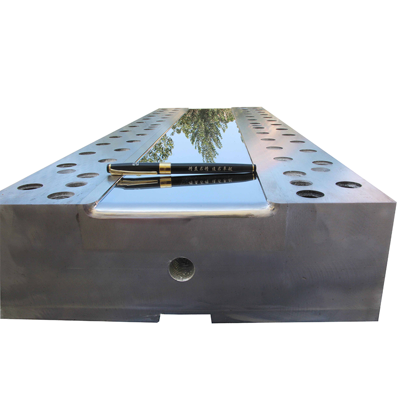
Chrome plating is nearly universal on production pultrusion dies. A hard chrome layer 25-50μm thick (micro-cracked, 900-1,000 HV hardness) reduces the coefficient of friction from 0.3-0.5 (steel on composite) to 0.1-0.15 (chrome on composite), cutting pulling force by 40-60% and extending die life 2-3x. The chrome must be stripped and replated after 200-500 km of production, depending on fiber type and filler content.
Dimensional Tolerances & Fabrication Constraints
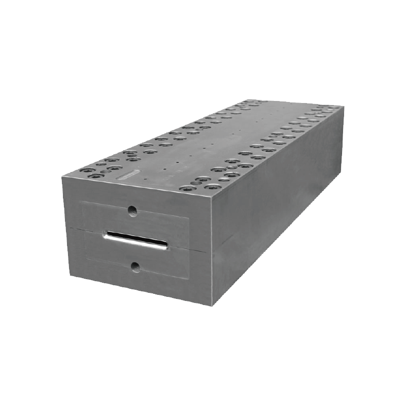
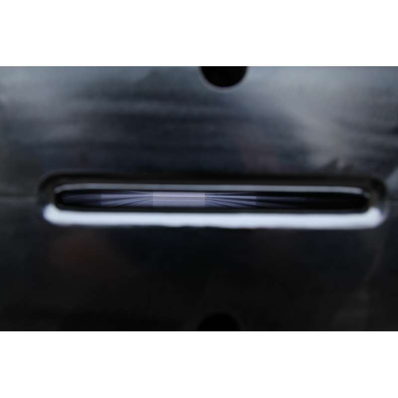
The die cavity is typically CNC machined from two halves (upper and lower) that bolt together to form the complete profile cross-section. Split-line placement is critical: it should be positioned at a corner or feature edge where a witness line is acceptable, never on a cosmetic surface. The two die halves are aligned using precision dowel pins (H7/g6 fit) and clamped with high-strength bolts torqued to 50-70% of yield.
Cavity surface finish directly transfers to the pultruded profile surface. For architectural and automotive profiles requiring Class A finish, the die cavity is polished to 0.2-0.4μm Ra using diamond paste, with the polishing direction aligned with the pulling direction (axial, never circumferential). Cross-hatch polishing patterns create micro-grooves that increase friction and cause surface streaking on the finished profile.
The entrance zone requires special attention to radii: all internal corners in the cavity should have a radius of at least 0.5mm — sharp corners create resin-rich zones, stress concentrations, and fiber damage as the fiber bundle is forced into the cavity. External corners (profile edges) should maintain a minimum radius of 0.3mm to prevent the chrome plating from chipping at sharp edges.
Heating System Design
Pultrusion dies are heated electrically using cartridge heaters or band heaters inserted into precision-bored holes in the die body. The heating system must deliver a precise temperature profile along the die length: typically 100-120°C at the entrance (to reduce resin viscosity without initiating cure), ramping to 140-180°C in the cure zone (depending on resin system), and holding at 160-200°C for the final 20-30% of die length to ensure complete cure.
Each heating zone is independently controlled by PID loops with thermocouples embedded 3-5mm from the cavity wall. A typical die has 3-6 heating zones along its length, each with 2-4 cartridge heaters. The design target is temperature uniformity of ±2°C across the entire cavity cross-section at any point along the die length. Zones where temperature deviates more than ±3°C produce uneven cure — the hotter side cures first, creating asymmetric shrinkage and warped profiles.
Die thermal analysis using FEA (finite element analysis) is standard practice for complex profiles. The simulation models heat transfer from cartridge heaters through the die body into the composite, accounting for the exothermic resin cure reaction (typically 200-400 J/g for unsaturated polyester). This analysis identifies cold spots — typically at internal corners and far from heater locations — that require additional heater placement or adjusted power distribution.
Design Checklist: 10 Points Before Finalizing
1. Verify cavity dimensions include allowance for composite shrinkage (0.2-0.5% linear for glass/polyester; 0.05-0.2% for carbon/epoxy) and die thermal expansion.
2. Confirm entrance taper angle (2-5° half-angle) and length produce a compaction ratio of 1.3-1.8:1 (incoming wet fiber volume to final cavity volume).
3. Check that the predicted gel point (from resin DSC kinetics and die thermal model) falls at 40-55% of total die length.
4. Verify chrome plating specification: 25-50μm micro-cracked hard chrome, 900-1,000 HV, polished to ≤0.4μm Ra in axial direction.
5. Ensure all internal corners have radius ≥0.5mm; all external corners have radius ≥0.3mm.
6. Confirm split line is placed at a non-cosmetic surface and sealed with high-temperature silicone or mechanical interlock.
7. Validate heating zone layout: 3-6 zones, thermocouples within 5mm of cavity wall, ±2°C uniformity target.
8. Check that heater watt density does not exceed 6 W/cm² for cartridge heaters in P20 steel (higher density causes localized overheating and reduced heater life).
9. Include thermocouple access ports at 3-5 positions along the die length for process monitoring.
10. Design the die mounting system to accommodate thermal expansion: one end fixed, one end floating on linear bearings with 2-3mm axial float.
What is a pultrusion die?
A pultrusion die is a precision-engineered heated tool that shapes, compacts, and cures continuous fiber-reinforced polymer profiles. It consists of a tapered entrance zone, a transition zone, and a straight heated curing zone, typically made from hardened tool steel with a chrome-plated cavity polished to sub-micron surface finish.
How long does a pultrusion die last?
A P20 steel die processing glass fiber profiles typically lasts 50-150 km of profile before requiring chrome re-plating, and 300-500 km before the cavity dimensions exceed tolerance. D2 steel dies for carbon fiber last 300-800 km. Carbide dies can exceed 2,000 km. Die life depends primarily on fiber type (carbon is 3-5x more abrasive than glass), filler content, and pulling speed.
Why does a pultrusion die need chrome plating?
Hard chrome plating (25-50μm, 900-1,000 HV) reduces the coefficient of friction between the curing composite and the die wall from 0.3-0.5 to 0.1-0.15, cutting pulling force by 40-60%. It also protects the steel substrate from chemical attack by acidic resin components and from abrasive wear by fiber and filler particles, extending die life 2-3x.
What is the cost of a pultrusion die?
A simple P20 steel pultrusion die for a small profile (under 500mm² cross-section, 600mm long) costs $15,000-30,000. A large, complex D2 steel die for a carbon fiber profile (over 10,000mm² cross-section, 1,200mm long, with 6 heating zones) costs $80,000-150,000. Carbide dies add a 10x multiplier. Chrome plating adds $2,000-5,000 per die. Die cost is amortized over production volume — at 100 km/year, a $50,000 die contributes $0.50/meter to product cost.