Injection mold problems during production are rarely mysterious. After maintaining molds for hundreds of injection molding projects over the years, we have seen the same patterns repeat. The crack in the cavity, the stuck slider, the flashing part—they all have the same few root causes. This article covers the most common mold maintenance issues we encounter and the fixes that actually work.
1. Mold flash / burr formation
Flash is the most frequent mold defect and the one that shuts down production fastest. It happens when molten plastic escapes the cavity through the parting line or moving interfaces. The usual suspects, in order of likelihood:
- Parting line damage. A small nick on the parting surface from a previous crash or improper handling creates a gap. Fix: stone the damage, check flatness with Prussian blue. If the damage is deeper than 0.05 mm, weld and re-machine.
- Clamp tonnage too low. This is the second most common cause. The mold is seeing more cavity pressure than the press can hold shut. Check the projected area against the machine’s clamp force rating—if the margin is under 15%, flash is likely.
- Vent channels blocked by residue. Over time, gas deposits build up in vent grooves and prevent air from escaping. This causes trapped gas that opens the parting line momentarily. Clean vents with a brass brush every 5,000–10,000 cycles depending on the resin.
- Mold not parallel. If the mold height is off by more than 0.02 mm from one corner to the opposite, the press will not clamp evenly. Always check parallelism with a feeler gauge during mold setup.
2. Ejector pin marks and sticking
When parts stick to the ejector side, operators often try to increase ejection speed or pressure. That rarely fixes the root cause. What actually causes sticking:
- Insufficient draft angle. Less than 0.5° per side for deep ribs causes the part to grip the core. For textured surfaces, add 1° per 0.025 mm of texture depth.
- Ejector pin wear. Pins wear faster on the return stroke than on the forward stroke. After 200,000 cycles, measure pin OD against the hole ID. If the clearance exceeds 0.03 mm, replace the pin.
- Mold surface too polished. A mirror finish on the core side actually increases friction. A surface finish of Ra 0.4–0.8 µm gives the best release for most engineering plastics.
- Uneven ejection force. If some pins push harder than others, the part tilts and binds. Check each pin for free movement—failed return springs are the usual culprit.
3. Slider and lifter failure
Slider jams are expensive. A stuck slider can damage the cavity and stop production for a full day. The causes are usually mechanical rather than process-related:
- Wear plate galling. Bronze wear plates against hardened steel slides work well—until the lubrication breaks down. We now use Graphite-plugged bronze wear plates on all high-cycle molds. They run dry for 50,000+ cycles without galling.
- Cooling line leakage. A pinhole leak in the slider cooling line causes water to mix with the lubricant on the slide face. The grease washes off and metal-to-metal contact starts. Pressure-test all slider cooling circuits before mold qualification.
- Spring failure. Return springs fatigue after 100,000–200,000 cycles. Replace them at scheduled maintenance intervals, not after failure.
- Debris in the slide track. Flash particles from previous runs fall into the slider track and jam the mechanism. Install a wiper seal at the front of the slider to keep debris out.
| Problem | Sign during production | First thing to check | Fix |
|---|---|---|---|
| Parting line flash | Thin plastic fins on the part edge | Parting line damage | Stone or weld the damaged area |
| Ejector pin sticking | Pin leaves a deep mark or part does not drop | Return spring condition | Replace worn springs |
| Slider jam | Slide does not retract fully | Wear plate condition | Replace with graphite-plugged bronze |
| Sink marks | Depression on thick wall sections | Cooling circuit flow rate | Descale or add conformal cooling |
| Short shot | Incomplete fill | Gate freeze-off or vent blockage | Check gate size and vent depth |
| Weld line visible | White line or weak point on the part | Melt temperature too low | Raise melt temp by 10–15°C or move gate |
The common thread across all these issues: maintenance is not a cost center, it is a cycle-life multiplier. A mold that gets regular preventive maintenance produces 30–40% more parts before major overhaul compared to one that runs until failure.
4. Cooling-related defects
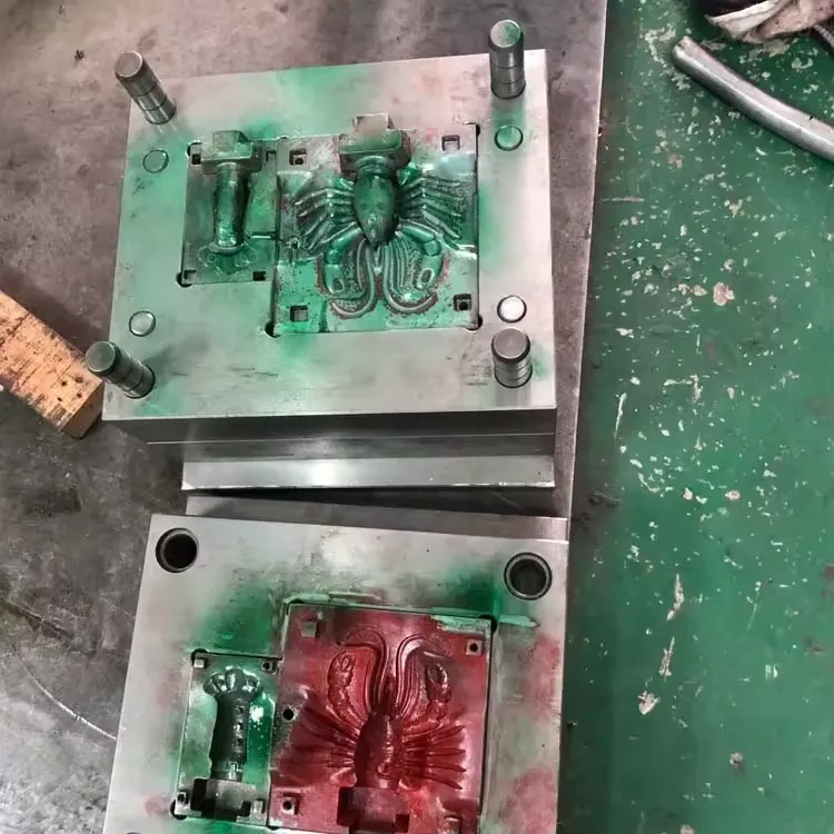
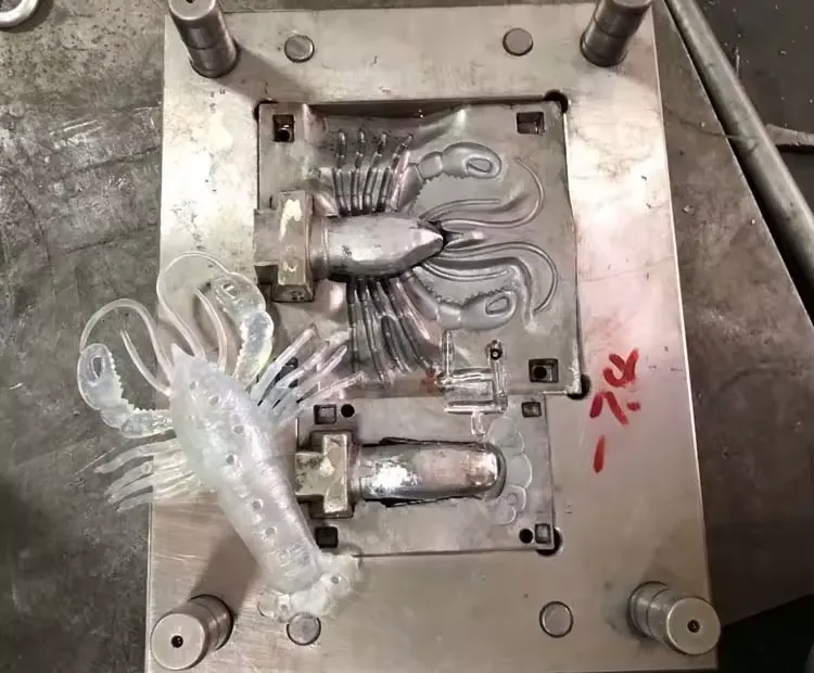
Sink marks, uneven shrinkage, and long cycle times are cooling problems, not material problems. The mold steel conducts heat—it does not generate it. If the cooling circuits are not removing heat efficiently, the process will not be stable regardless of the melt temperature or injection speed.
Causes we see most often: Cooling channels too far from the cavity surface (more than 2x the channel diameter), mineral scale buildup inside the channels (which reduces heat transfer by up to 60%), and unbalanced flow between cavity and core circuits.
The fix: Measure flow rate through each cooling circuit individually. If two circuits on the same mold show more than 15% variation, the flow is unbalanced. Use flow regulators on the return side. For existing molds with scale, flushing with a citric acid solution at 60°C for 4 hours restores 80–90% of the original heat transfer.
5. Wear on guide pins and bushings
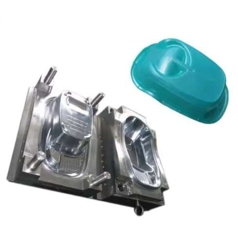
Worn guide components affect mold alignment and cause flash on one side of the part. The wear pattern is always the same: the pin wears on the load-bearing side, creating an oval shape. Once the clearance exceeds 0.03 mm, the alignment shifts.
Prevention: Apply grease every 2,000 cycles through a central lubrication system. Replace guide pins and bushings as a matched set—mixing new pins with worn bushings accelerates wear on the new pin. For high-cavitation molds, consider guided ejection systems that take alignment load off the main guide pins.
Preventive maintenance schedule that works
The schedule that keeps our molds running with minimal downtime:
- Every 5,000 cycles: Clean vent grooves, check guide pin clearance, lubricate all moving parts
- Every 20,000 cycles: Pressure-test cooling circuits, check parallelism, inspect ejector pins
- Every 100,000 cycles: Replace return springs, check wear plate condition, measure cooling channel scale
- Every 200,000 cycles: Replace guide pins/bushings, re-polish cavity surfaces if needed
This schedule assumes standard engineering plastics (ABS, PP, PC, PA6). Glass-filled or flame-retardant grades require intervals 30–50% shorter. Running a mold beyond these intervals without inspection is the single biggest cause of unexpected downtime.
For more on mold design and steel selection, see our mold steel selection guide and injection mold design guide. Industry background on mold maintenance is available from PlasticsToday.
Frequently asked questions
How often should injection molds be serviced?
Every 5,000–10,000 cycles for preventive maintenance, depending on the resin type. Glass-filled materials need more frequent service. Running a mold beyond 15,000 cycles without inspection risks damage that costs more to repair than the maintenance schedule does.
What causes flash on the parting line?
Either the parting surface is damaged, the clamp force is too low, or vent channels are blocked. The fastest diagnosis: close the mold on a piece of carbon paper. If the contact pattern is uneven, resurface the parting area.
Why do sliders stick after several months of production?
Usually wear plate galling or dried-out lubrication. Take the slider out and inspect the wear plate. If it shows copper smearing, replace it with graphite-plugged bronze and install a central lubrication line to the slide face.
Can sink marks be fixed by adjusting the packing pressure?
Sometimes, but it is a band-aid. If the sink mark is on a thick section (above 4 mm), the root cause is insufficient cooling near that area. Add conformal cooling or a thermal pin in the core at the thick section.
When should guide pins be replaced?
When the clearance between pin and bushing exceeds 0.03 mm. Measure with a feeler gauge at the bushing mouth. Replace as a matched set. A worn bushing on one side can side-load the new pin and cause premature failure.
Standards & References
The following industry standards are referenced in this article: