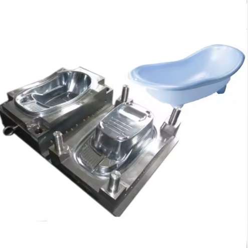
Injection molding remains one of the most widely used manufacturing processes for producing plastic components across industries ranging from automotive and consumer goods to medical devices and electronics. The quality, efficiency, and cost-effectiveness of any injection molding operation depend fundamentally on the quality of the mold design. A well-designed mold ensures consistent part quality, optimal cycle times, and extended tool life, while a poorly designed mold leads to defects, downtime, and excessive maintenance costs.
This comprehensive guide covers the essential aspects of injection mold design, providing manufacturing engineers, mold designers, and procurement professionals with the technical knowledge needed to specify, evaluate, and maintain high-performance injection molds. For an overview of our complete injection mold manufacturing capabilities, visit our homepage.
Fundamentals of Injection Mold Design
Injection mold design encompasses a broad range of engineering disciplines, including material science, thermal dynamics, fluid mechanics, and mechanical design. The primary function of an injection mold is to receive molten plastic from the injection molding machine, distribute it through a runner system, fill the cavity cavity, cool the part to solidification, and eject the finished component. Each of these functions requires careful design consideration to achieve optimal results.
The design process begins with a thorough analysis of the part geometry, material selection, production volume, and quality requirements. These factors determine the mold configuration, number of cavities, gate type and location, cooling system design, and ejection mechanism. A systematic approach to mold design reduces trial-and-error during mold commissioning and ensures consistent production performance.
Key Components of an Injection Mold
Understanding the function of each mold component is essential for effective design. The following table summarizes the primary components and their functions:
| Component | Function | Design Considerations |
|---|---|---|
| Mold Base | Provides structural support and alignment | Size, material, standard vs. custom |
| Cavity and Core | Forms the part shape (cavity = exterior, core = interior) | Steel grade, surface finish, venting |
| Runner System | Distributes molten plastic to cavities | Cold vs. hot runner, gate type, flow balance |
| Gate | Controls plastic flow into the cavity | Position, size, type (edge, pin, tunnel, fan) |
| Cooling System | Removes heat from the molded part | Cooling channel layout, diameter, flow rate |
| Ejection System | Removes the finished part from the core | Ejector pins, sleeves, stripper plates, air ejection |
| Venting System | Allows trapped air and gases to escape | Vent depth, location, cleanliness |
Critical Design Parameters
1. Cavity and Core Design
The cavity and core are the heart of the injection mold. The cavity forms the exterior surface of the part, while the core forms the interior features. The selection of appropriate steel grades is critical for mold longevity and part quality. For high-volume production, hardened tool steels such as P20, H13, or 420 stainless steel provide the wear resistance and hardness required to withstand millions of cycles. For prototype or low-volume production, softer steels or aluminum may be acceptable.
Surface finish requirements directly influence mold manufacturing complexity. A polished mirror finish requires premium steel grades and extensive hand polishing work, while textured finishes can be achieved through electrical discharge machining (EDM) or chemical etching. The surface finish specification should match the part’s functional and aesthetic requirements without over-specifying.
2. Runner System Design
The runner system delivers molten plastic from the machine nozzle to the cavity gates. Two primary runner types exist: cold runners and hot runners. Cold runners are simpler and less expensive but generate waste material (regrind). Hot runners maintain the plastic in a molten state within the manifold, eliminating runner waste and reducing cycle times. The runner cross-section should be designed to minimize pressure drop while maintaining adequate flow volume. Trapezoidal or full-round cross-sections provide optimal flow characteristics.
For multi-cavity molds, flow balance is essential to ensure all cavities fill simultaneously and produce consistent parts. Natural flow balancing through geometric symmetry is preferred, but artificial balancing using gate size adjustments is sometimes necessary for irregular layouts.
3. Cooling System Design
Cooling typically accounts for approximately 60-80% of the total cycle time in injection molding. An efficient cooling system directly improves productivity and part quality. Cooling channels should be positioned as close to the cavity surface as possible (typically 2-3 times the channel diameter from the surface) and follow the part contour for uniform heat removal.
Key parameters for cooling system design include:
- Cooling channel diameter typically 8-14 mm
- Distance between channels: 3-5 times channel diameter
- Distance from cavity surface: 2-3 times channel diameter
- Turbulent flow (Reynolds number > 4000) for maximum heat transfer
- Baffles and thermal pins for deep core cooling
- Conformal cooling channels for complex geometries (additive manufacturing)
4. Ejection System Design
Proper ejection system design ensures that the finished part is removed from the mold without damage or distortion. Standard ejection methods include ejector pins (round or blade), ejector sleeves, stripper plates, and air ejection. The ejection system must provide sufficient ejection force and stroke length while distributing force evenly across the part surface to prevent marking or deformation.
Ejector pin placement should be concentrated in areas where the part tends to stick to the core, such as deep ribs, bosses, and areas with significant undercut. The draft angle of the part also significantly influences ejection force; a minimum draft angle of 1-2 degrees per side for general-purpose parts is recommended.
Material Selection for Mold Components
Selecting the right steel grade for each mold component is a critical decision that affects mold cost, lead time, and service life. The following table provides guidance for material selection based on application requirements:
| Steel Grade | Hardness (HRC) | Applications | Key Properties |
|---|---|---|---|
| P20 | 28-32 | Cavities and cores for general-purpose molding | Good polishability, machinability |
| H13 | 46-50 | High-wear applications, slide cores | Excellent wear resistance, toughness |
| 420 SS | 48-52 | Corrosive plastics (PVC, flame retardant) | Corrosion resistance, polishability |
| S136 | 48-52 | Optical and medical components | Superior mirror finish, corrosion resistance |
| NAK80 | 37-43 | Textured surfaces, display panels | Pre-hardened, excellent texture retention |
| 718 | 30-34 | Large cavities, high-production molds | High toughness, good machinability |
Common Mold Design Defects and Solutions
Even experienced mold designers encounter common design-related defects during mold commissioning. The following troubleshooting guide addresses the most frequent issues:
| Defect | Root Cause | Design Solution |
|---|---|---|
| Short Shot | Insufficient flow, trapped air | Increase gate size, add vents, modify runner balance |
| Flash | Insufficient clamp force, worn mold surfaces | Increase steel hardness, improve mold alignment, balance pressure |
| Sink Marks | Insufficient packing in thick sections | Add cooling near thick areas, increase gate size, reduce thickness |
| Weld Lines | Flow fronts meeting at low temperature | Relocate gates, add flow leaders, increase melt temperature |
| Warpage | Non-uniform cooling or shrinkage | Balance cooling channels, optimize part geometry, use fillers |
| Burn Marks | Trapped air compressing and igniting | Improve venting, reduce injection speed, add vacuum venting |
Hot Runner vs Cold Runner Systems
The choice between hot runner and cold runner systems has significant implications for mold design, cost, and production efficiency. Here are the key trade-offs:
- Hot Runner Systems — Eliminate runner waste, reduce cycle times (no runner cooling required), enable faster mold opening, and provide better gate vestige control. However, they are 30-50% more expensive than equivalent cold runner molds, require more maintenance, and introduce color-change challenges. Ideal for high-volume production of commodity parts.
- Cold Runner Systems — Lower initial cost, simpler construction, easier color changes, and lower maintenance requirements. The primary disadvantage is material waste (regrind), longer cycle times, and larger machine size requirements due to runner volume. Suitable for medium-volume production, frequent material changes, and applications where regrind usage is acceptable.
Industry standards for hot runner system design and temperature control follow established guidelines from PLASTICS (Plastics Industry Association) for machine and mold compatibility requirements.
Mold Flow Analysis and Simulation
Modern mold design relies heavily on computer-aided engineering (CAE) simulation tools to predict material flow, cooling behavior, and part quality before steel cutting begins. Mold flow analysis provides critical insights into:
- Fill pattern and potential weld line locations
- Air trap locations requiring venting
- Pressure distribution and required clamp force
- Cooling channel effectiveness and temperature distribution
- Shrinkage and warpage prediction
- Gate freeze-off timing and packing analysis
Simulation reduces mold commissioning time by 30-50% and significantly reduces the risk of costly design errors. For high-precision components such as automotive and medical parts, mold flow analysis is considered an essential step in the design process. Material property databases such as those provided by MatWeb material property database provide the input data required for accurate simulation results.

/figure>
Quality Control in Mold Manufacturing
Rigorous quality control throughout the mold manufacturing process ensures that the finished mold meets design specifications and performs reliably in production. Key quality control points include:
- Design Review — DFM (Design for Manufacturing) analysis, gate position optimization, cooling analysis, and ejection analysis before machining begins
- Steel Verification — Material certification, hardness testing, and flaw detection for all mold components
- Machining Inspection — CMM (Coordinate Measuring Machine) verification of critical dimensions, surface finish measurement, and fit check for moving components
- Assembly and Bench Testing — Mold base assembly, slide and lifter function, cooling circuit pressure test, and ejection system stroke verification
- Trial Molding — Process parameter development, dimensional validation of first articles, cosmetic inspection, and mold performance evaluation. For details on our mold factory quality standards, visit our about us page.
Conclusion
Injection mold design is a complex engineering discipline that requires deep knowledge of material science, thermal management, fluid dynamics, and manufacturing processes. A successful mold design balances competing requirements for part quality, cycle time, tool life, and manufacturing cost. By understanding the fundamentals of cavity and core design, runner systems, cooling optimization, ejection mechanisms, and material selection, engineers can develop molds that perform reliably and efficiently.
At Tstar Mold, we specialize in designing and manufacturing high-precision injection molds for the automotive, medical, appliance, and consumer goods industries. Our engineering team combines advanced simulation technology with decades of practical experience to deliver molds that meet the most demanding production requirements. Contact our team to discuss your mold design project.
Frequently Asked Questions (FAQ)
What is the typical lead time for an injection mold? Standard lead times range from 4 to 12 weeks depending on mold complexity, cavity count, and steel availability. Simple two-plate molds with single cavities can be completed in 4-6 weeks, while complex multi-cavity molds with hot runner systems and slides require 8-12 weeks.
How long does an injection mold last? Mold life depends on several factors including steel grade, production material, maintenance quality, and operating conditions. P20 steel molds typically produce 500,000 to 1 million cycles. H13 and S136 molds can exceed 2 million cycles with proper maintenance. For prototype and low-volume production, aluminum molds are suitable for 10,000 to 100,000 cycles.
What is the difference between a 2-plate and 3-plate mold? A 2-plate mold has a single parting line and is the simplest and most common configuration. A 3-plate mold has two parting lines, allowing the runner system to be separated from the part automatically. 3-plate molds are preferred when center gating is required or when the runner system must be mechanically separated from the molded part before ejection.
How do I choose between cold runner and hot runner? Choose a hot runner when: high-volume production (over 100,000 parts per year), automated molding, strict gate vestige requirements, or processing expensive engineering plastics. Choose a cold runner when: lower initial mold cost is critical, frequent material or color changes are expected, or the production volume does not justify the hot runner investment.
What draft angle is recommended for injection molding? A minimum draft angle of 1-2 degrees per side is recommended for general-purpose parts. Shallow textured surfaces require 3-5 degrees, while deep ribs and bosses may need 0.5-1 degree per side. Insufficient draft angle increases ejection force and can cause part sticking or surface damage.
Can you retrofit an existing mold with a hot runner system? In many cases, yes. Retrofitting involves replacing the cold runner with a hot half assembly. However, the feasibility depends on the existing mold base size, cavity layout, and available machine platen space. A feasibility study should be conducted before proceeding with a retrofit. Contact our engineering team to evaluate your specific mold configuration.
Standards & References
The following industry standards are referenced in this article: