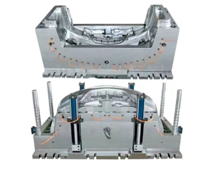
A mold maker in Taizhou cut a new SMC enclosure mold to the customer’s nominal dimensions — exactly as specified on the 3D model. First shots came out 0.23mm undersized on a 200mm span. That’s a 0.115% miss. On the print, it was just barely inside tolerance. Stack that across four mounting bosses and the bolt holes didn’t line up with the mating part. The mold went back to the CNC for a re-cut. The shop ate the $4,800 rework cost.
SMC shrinkage is small. But small gets amplified by part geometry, fiber orientation, and mold temperature gradients. A 0.05% shrinkage error on a 400mm part is 0.2mm — enough to fail a ±0.15mm dimensional tolerance. Get the compensation right at the mold design stage and your parts drop in spec from the first shot. Get it wrong and you’re chasing dimensions through process adjustments that can only fix about half the error.
Design Parameters & Performance Requirements
Shrinkage in SMC comes from three sources, and they happen at different points in the molding cycle. Understanding which one dominates your part is the first step toward compensating for it.
Chemical shrinkage (cure shrinkage). The polyester resin crosslinks during cure. Linear polymer chains form a three-dimensional network, which takes up less volume. This is the biggest contributor, typically accounting for 60-75% of total shrinkage. The amount depends on the resin chemistry — vinyl ester shrinks about 10-15% more than orthophthalic polyester because it crosslinks more densely. Low-profile additives (thermoplastic particles like PVAc, PMMA, or polystyrene dissolved in styrene) reduce chemical shrinkage by creating microvoids that absorb volume change during cure. A good low-profile additive knocks total shrinkage from 0.3-0.4% down to 0.05-0.1%, or even to near-zero in some formulations.
Thermal contraction. The part cures at 140-160°C and cools to ambient. The coefficient of thermal expansion (CTE) for SMC is 12-20 × 10⁻⁶/°C in the in-plane direction and 30-50 × 10⁻⁶/°C through-thickness. A 130°C temperature drop at CTE of 15 × 10⁻⁶/°C gives 0.195% thermal contraction. This is predictable and linear — once you know the mold temperature and the material CTE, you can calculate it exactly.
Fiber relaxation. Glass fibers are elastic. During molding, the fibers are compressed and slightly bent as the material flows through the cavity. When the press opens and the part is ejected, the fibers relax — the part springs back a few microns. This is the smallest component (0.01-0.03%) and the hardest to predict because it depends on fiber orientation, which depends on flow, which depends on charge placement and mold closing speed.
Total shrinkage for a standard SMC formulation without low-profile additives: 0.15-0.40%. With low-profile additives: 0.00-0.10%. The catch: low-profile additives trade shrinkage reduction for surface quality and mechanical properties. Too much LPA and you get microvoids big enough to affect paint adhesion and reduce flexural strength 10-15%.
“We used to add a blanket 0.3% to all our mold cavities and call it good. Worked fine for simple blocks. Then we got a complex battery enclosure with 15 ribs in three directions. The ribs came out 0.15mm off-position because the shrinkage was anisotropic — different in the rib direction than across it. Now we do flow simulation and compensate per-feature.” — Mold design engineer, Taizhou
Load Calculations & Structural Analysis
Shrinkage compensation isn’t just about scaling the entire cavity uniformly. Shrinkage is anisotropic — it varies with fiber orientation, which varies with flow direction. A flat, simple-shape part with uniform flow shrinks uniformly. A complex part with ribs, bosses, and thickness transitions shrinks unevenly.
Isotropic vs anisotropic compensation. For parts with simple geometry and no significant flow orientation, you apply a uniform scaling factor to the mold cavity. The rule of thumb: mold dimension = part dimension × (1 + shrinkage_rate). For a part dimension of 200.00mm and 0.25% shrinkage: mold = 200.00 × 1.0025 = 200.50mm.
For anisotropic compensation, you need direction-specific shrinkage factors. The shrinkage in the flow direction (fiber-aligned direction) is typically 30-50% lower than the cross-flow direction because glass fibers constrain the resin shrinkage along their axis. A typical ratio: 0.15% in the flow direction vs 0.30% cross-flow. Applying a uniform 0.25% leaves you 0.10% undersized in the flow direction and 0.05% oversized cross-flow.
Rib shrinkage. Ribs are the troublemakers. A rib perpendicular to the main wall shrinks in three dimensions — along its length, across its width, and through its thickness. The through-thickness shrinkage pulls the rib away from the mold wall, which can cause sink marks on the opposite surface. The cure-shrinkage-driven warpage of ribs can pull a flat wall out of plane by 0.1-0.3mm per 100mm of rib length. The fix: rib draft angles of 1.5-2° (not the 0.5-1° used for injection molding) and generous radii at the rib-wall junction (minimum 2× wall thickness) to reduce the stress concentration that amplifies warpage.
Boss shrinkage. A boss — a cylindrical protrusion for a threaded insert or self-tapping screw — shrinks radially onto the core pin. If the shrinkage is 0.25% and the boss ID is 8.00mm, the boss shrinks 0.02mm radially, gripping the core pin. Ejection force goes up. The fix is adding 0.02-0.03mm to the core pin diameter per side, or using a stripper plate ejection that pushes uniformly around the boss perimeter instead of pin ejection that concentrates force at a point.
Material Selection: Properties Comparison Matrix
Different SMC formulations shrink differently. Here’s the data for common grades.
| SMC Grade | Linear Shrinkage (%) | With LPA (%) | Flexural Strength (MPa) | CTE (×10⁻⁶/°C) | Typical Use |
|---|---|---|---|---|---|
| General Purpose (GP) | 0.25-0.40 | 0.05-0.10 | 150-200 | 14-18 | Non-appearance structural |
| Low-Profile (LP) | 0.15-0.30 | 0.00-0.05 | 140-180 | 14-18 | Class A automotive exterior |
| Electrical Grade | 0.20-0.35 | 0.03-0.08 | 120-160 | 12-16 | Switchgear, enclosures |
| Structural (High Glass) | 0.10-0.20 | 0.00-0.05 | 200-280 | 12-15 | Load-bearing, 35%+ glass |
| Flame Retardant (ATH-filled) | 0.20-0.30 | 0.05-0.10 | 100-140 | 16-22 | UL 94 V-0 applications |
| Vinyl Ester VE | 0.30-0.50 | 0.05-0.15 | 160-220 | 15-20 | Chemical/corrosion resistant |
High-glass structural SMC shrinks the least because glass fibers don’t shrink — only the resin does. More glass = less resin volume = less total shrinkage. But high-glass SMC flows less easily in the mold, which limits how complex a geometry you can fill. It’s a three-way tradeoff: shrinkage, flow, and strength. Pick two.
Flame-retardant grades with ATH (alumina trihydrate) filler have higher filler loading (35-50%), which adds more non-shrinking solid volume and reduces overall shrinkage. But the thermal conductivity goes up, which means the part cools faster in the mold — and thermal contraction happens faster than the resin can stress-relieve. This can lead to higher internal residual stress, which shows up as warpage after ejection.
Dimensional Tolerances & Fabrication Constraints
SMC compression molding is not injection molding. The tolerances achievable are different, and pretending otherwise leads to mold rework.
Achievable tolerances without LPA: ±0.10mm for dimensions under 50mm. ±0.15-0.25mm for 50-200mm. ±0.25-0.50mm for 200-500mm. These numbers assume the mold is cut with shrinkage compensation at the material’s nominal shrinkage rate. They also assume consistent molding conditions — charge weight within ±2%, mold temperature within ±3°C, and cure time within ±15 seconds.
Achievable tolerances with LPA: ±0.05mm for dimensions under 50mm. ±0.10-0.15mm for 50-200mm. ±0.15-0.25mm for 200-500mm. LPA effectively removes chemical shrinkage from the equation, leaving thermal contraction and fiber relaxation as the remaining variables. Both are more predictable than chemical shrinkage.
Parting line and flash allowance. SMC molds generate flash — resin-rich overflow at the parting line and around ejector pins. The flash thickness is typically 0.05-0.15mm. If your tolerance stack assumes parting-line dimensions are zero-clearance, you’ll get parts that don’t fit. Allow 0.10mm per parting line for flash in the tolerance budget.
Steel selection for the mold. P20 is the default SMC mold steel — HRC 28-32, machines easily, polishes to SPI A-3 finish. For high-volume molds (100,000+ cycles), H13 (HRC 48-52) resists wear at the flow fronts better and maintains cavity dimensions longer. The steel CTE matters for hot molds: the mold cavity is cut at room temperature but operates at 140-160°C. P20 expands 0.0013 mm/mm at 150°C. A 500mm cavity grows about 0.65mm between room temperature and operating temperature. The cavity must be cut undersized at room temperature so that it’s the correct dimension at molding temperature.
Integration Design: Interfaces, Fasteners & Sealing
Shrinkage compensation doesn’t end at the part boundary. Mating parts, inserts, and seals all have to work with the as-molded dimensions.
Molded-in inserts. Threaded brass or steel inserts placed in the mold before the SMC charge is added. The SMC shrinks around the insert during cure, creating a mechanical lock. But the insert also acts as a local heat sink — it’s at room temperature when it goes into a 150°C mold. The SMC around the insert cures slower because the insert chills the local resin. This creates a gradient in cure shrinkage: lower shrinkage near the insert (less cure = less crosslinking), higher shrinkage away from it. The result is a zone of residual tensile stress around the insert that can cause microcracking. Preheating inserts to 80-100°C before placement reduces this gradient.
Snap-fit features. SMC can do snap fits, but the design has to respect the material’s elongation at break (1.0-1.5% for standard SMC, vs 3-5% for unfilled thermoplastics). The snap arm deflection needs to stay under 0.8% strain to leave margin for fatigue. A 20mm-long snap arm in SMC can deflect about 0.20-0.25mm at the tip safely. For a thermoplastic, that same arm could deflect 0.60-0.80mm. If you’re converting a thermoplastic part to SMC, the snap fits almost certainly need to be redesigned — you can’t just swap materials and ship the same tool geometry.
Sealing surfaces. An O-ring groove molded into SMC will shrink 0.1-0.3% from the mold dimension. An 80mm-diameter groove shrinks 0.08-0.24mm in diameter. The O-ring gland depth changes by the same percentage. If the gland was designed for nominal dimensions without compensation, the O-ring compression ratio will be off by 2-5 percentage points — enough to turn a seal into a leak path. Add shrinkage compensation to all seal features, and include O-ring groove dimensional inspection in the first-article check.
Testing & Validation Protocols
First-article inspection catches shrinkage errors. Process capability catches shrinkage variation.
First-article dimensional inspection. Measure every dimension on the first 5-10 parts off the mold. Use a CMM or 3D scanner — calipers aren’t accurate enough for the sub-0.10mm level. Compare measured dimensions to the print. The shrinkage ratio for each feature = (mold_dimension – part_dimension) / mold_dimension. If different features show different shrinkage ratios, you have an anisotropic shrinkage problem — flow simulation or mold modification needed.
Process capability study. Once the mold is dialed in, run 30 consecutive shots and measure the critical dimensions on each. Calculate Cp and Cpk for each critical dimension. A Cpk below 1.33 on a dimension means the process variation + mean shift is eating more than 0.01% of the tolerance band — you need either tighter process control or a mold modification to center the mean.
Thermal stability check. Run 50 shots, measure the critical dimension on shot #1, #25, and #50. If the dimension drifts more than 0.05mm, the mold temperature control isn’t stable. Check for: coolant flow variation in parallel circuits (one circuit stealing flow from another), thermocouple placement (too close to the heater vs too close to the cavity surface), or ambient temperature swings in the shop affecting the cooling side of the thermal cycle.
Warpage measurement. Place the part on a surface plate. Measure the gap under the part at specified locations using feeler gauges or a dial indicator. A gap over 0.2mm per 100mm of span usually indicates a cure imbalance — one side of the mold cured faster than the other, creating asymmetric shrinkage through the part thickness. The fix: balance the heating circuits or adjust the charge placement to fill the cavity more symmetrically.
Design Checklist: 10 Points Before Finalizing
- Shrinkage rate confirmed for your specific SMC grade. Use the material supplier’s datasheet number, not “typical SMC.” Test it on a flat plaque mold if the supplier hasn’t published data for your specific formulation.
- Low-profile additive decision documented. Yes LPA = near-zero shrinkage but lower mechanicals and potential paint issues. No LPA = simpler but 0.15-0.40% shrinkage. Document the tradeoff.
- Anisotropic shrinkage evaluated for flow-aligned features. If the part has ribs, long walls, or complex flow paths, run a flow simulation with shrinkage prediction — don’t assume isotropic behavior.
- Mold steel thermal expansion factored into cavity dimensions. The cavity is cut at 20°C and runs at 150°C. P20 expands 0.0013mm/mm over that range. Include it in the compensation stack.
- Rib draft angles at 1.5-2° minimum. SMC shrinks onto mold cores more aggressively than thermoplastics. Tighter draft angles than 1.5° will cause ejection problems.
- Boss cores oversized by shrinkage amount plus 0.02mm. Radial shrinkage onto the core pin increases ejection force. Compensate the pin diameter.
- Parting line flash allowance in tolerance budget. 0.10mm per parting line for flash thickness. Include it.
- Insert preheat specified if molded-in inserts used. Cold inserts create a local cure gradient and residual stress around the insert. Preheat to 80-100°C.
- O-ring/seal gland dimensions compensated. A 0.2% shrinkage on a seal gland changes the compression ratio enough to leak. Compensate and verify at first article.
- First-article inspection plan ready with CMM or 3D scan. calipers won’t cut it for sub-0.10mm tolerance validation. Plan the metrology before the mold steel is cut.