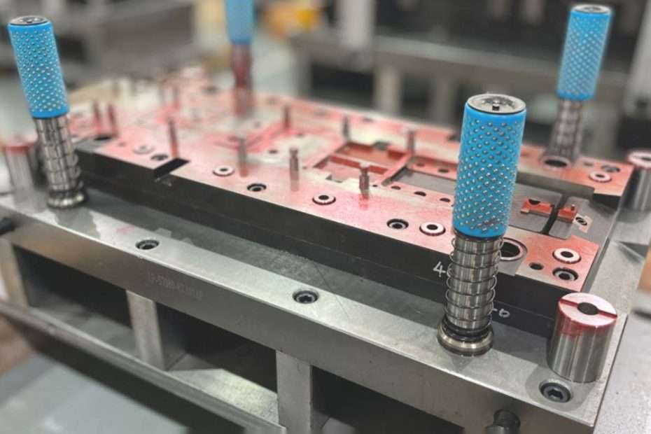
A brand-new SMC compression mold costs $50,000 to $150,000 and took twelve weeks to design, machine, polish, and fit. It arrives at the molding facility on a flatbed truck. The receiving inspection takes two hours—visual check, a few spot dimensions, the mold certification paperwork signed off. Then someone bolts it into a 500-ton press, programs the mold temperature controller to 135°C, loads the first charge of SMC material, and hits cycle start. In about five minutes, every shortcut in the mold design, every tolerance stack-up that nobody caught at the design review, every cooling channel that got placed too close to the cavity edge, and every assumption about material flow that was never simulated—all of it becomes physical reality in the form of a hot, cured SMC part sitting on the ejector pins. The first article inspection isn’t a quality checkbox. It’s the only structured opportunity to prove that a six-figure tool will produce in-spec parts for the next ten years, before the production schedule depends on it. Done right, a mold tryout catches the problems that cost $5,000 to fix today versus $50,000 to fix after production ramp-up. Done wrong—or skipped because the project is behind schedule—and you’ll be welding and re-machining hardened P20 steel six months from now, explaining to your customer why shipments are delayed. This article covers the full tryout-to-FAI workflow: what to verify before the first shot, how to map a process window, how to validate dimensions against CAD, how to run a capability study, and how to package the results into an FAI report that survives a customer audit.
 AS9102 tool qualification” />
 AS9102 tool qualification” />
What Is SMC Mold Tryout and Validation — Material Science & Engineering Principles
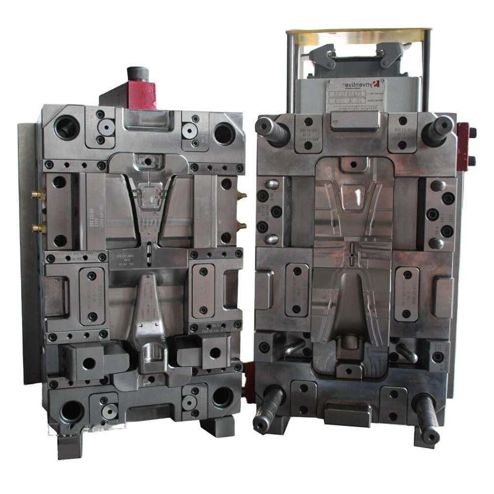
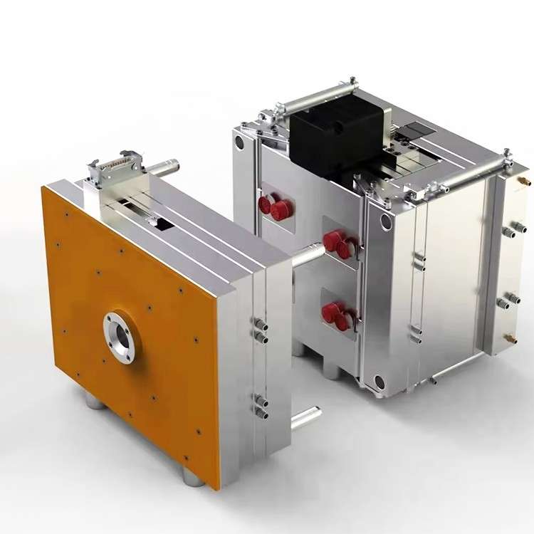
SMC mold tryout is the systematic process of installing a new or modified compression mold into a production press, running SMC material through it under controlled conditions, and validating that the resulting parts meet every dimensional, mechanical, and visual requirement on the engineering drawing. It’s distinct from injection mold tryout in several important ways. SMC is a thickened, fiber-filled thermoset compound that flows under heat and pressure—its viscosity profile during molding is nothing like a thermoplastic melt. The material arrives at the press as a leathery sheet, is cut to a specific charge weight and pattern, placed onto the lower mold half, and compressed. Under heat (130-150°C for epoxy SMC) and pressure (5-25 MPa), the resin viscosity drops, the charge flows outward to fill the cavity, and the crosslinking reaction begins. Flow stops when the cavity is full or the resin gels—whichever happens first. If the resin gels before the cavity is completely filled, the part is scrap. This time-pressure-temperature-cure interplay is unique to thermoset compression molding and is why SMC tryout requires a different approach than thermoplastic injection molding. The tryout has five sequential phases: pre-tryout verification (does the mold fit the press and are all the auxiliary systems working), process window mapping (what combination of temperature, pressure, and charge pattern produces a fully filled part), dimensional validation (does the part from the center of the process window match the CAD model), capability study (can the process produce conforming parts consistently over a production-length run), and FAI documentation (the formal report package that proves all of the above to the customer). Skipping or compressing any of these phases to meet a deadline is the most common cause of production quality problems traced back to mold qualification.
The single most expensive day in the life of an SMC mold is the day of the first shot—not because anything went wrong, but because everything is unknown. The mold hasn’t seen material. The press hasn’t felt the tool. The process parameters are educated guesses from the material supplier’s datasheet. Every hour of tryout time costs press time, operator time, and project schedule. The pre-tryout checklist exists to eliminate the unknowns that can be eliminated before the mold ever sees the press.
| Tryout Phase | Key Activities | Typical Duration | Output Document |
|---|---|---|---|
| Pre-Tryout Verification | Mold dimensional spot-check, cooling/heating circuit leak test, press fitment, SMC material batch certification, auxiliary equipment checkout | 4-8 hours | Mold certification checklist with sign-offs |
| Process Window Mapping | Systematic variation of temperature, pressure, and charge coverage; 15-25 short runs evaluating fill, surface, and Barcol hardness | 1-2 days | Process window definition with parameter envelope |
| Dimensional Validation | Full CMM or 3D scan of 5-10 parts from process window center; comparison to CAD nominal with tolerance evaluation | 1-2 days | Dimensional inspection report with deviation map |
| Capability Study | 30-piece continuous run at optimized parameters; Cp/Cpk calculation on 8-12 critical dimensions | 4-8 hours | Process capability report with Cpk values |
| FAI Documentation | AS9102 Form 1/2/3 or customer-specific FAI report; assembly of all prior-phase reports | 1-2 days | Completed FAI package ready for customer review |
Performance Data & Mechanical Properties
The tryout doesn’t just verify geometry—it verifies that the molding process produces parts with the mechanical properties the part was designed around. For SMC parts, the key mechanical indicators to check during tryout are Barcol hardness (a quick surface hardness test that correlates with degree of cure), part weight (a sensitive check on charge weight consistency and material loss to flash), and—if the part is structural—tensile or flexural strength from a molded-in coupon or a section cut from a sacrificial part. Barcol hardness is the frontline check. A fully cured epoxy SMC part should read 50-65 on the Barcol 934-1 scale, depending on the resin formulation. Readings below 45 indicate under-cure: the resin hasn’t crosslinked enough, and the mechanical properties, chemical resistance, and elevated-temperature performance will all be below spec. The corrective action is usually increasing mold temperature or extending cure time—but first verify that the mold temperature controller is reading accurately with an independent surface thermocouple pressed against the cavity surface. A common tryout mistake is chasing low Barcol readings for an entire shift before discovering the mold’s thermocouple was reading 10°C high and the actual cavity temperature was 10°C below the setpoint. Part weight is the simplest and most revealing process indicator. Weigh every part from the process window study. The weight should be consistent within ±1-2% across consecutive shots. Increasing weight trend suggests SMC material is thickening (advancing in maturation) over the course of the tryout and flowing less, leaving more material in the cavity. Decreasing weight trend suggests the opposite—material is softening with ambient heat and flowing more, squeezing more flash out of the parting line. A weight range exceeding ±3% across a capability study run indicates a process control problem that will show up later as dimensional variation. For structural SMC parts, the tryout should include destructive testing of at least three parts—cut tensile or flexural coupons from designated locations on the part (typically flat sections away from ribs and bosses) and test per ASTM D3039 or D790. The measured values should fall within the range published on the SMC supplier’s TDS. If they don’t—if the tryout parts are consistently 10-15% below the TDS values—the likely causes are under-cure, poor fiber wet-out due to insufficient pressure, or fiber orientation in the part differing from the supplier’s test plaque due to flow during mold filling.
Manufacturing Process & Quality Control
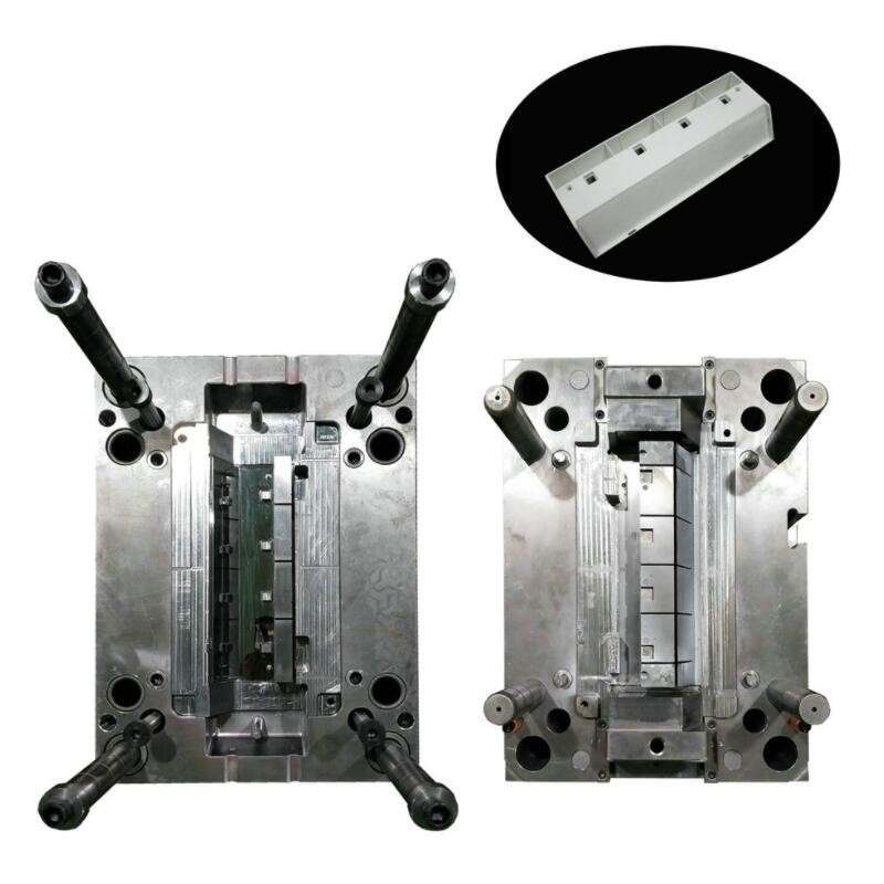
The SMC mold tryout workflow begins with the pre-tryout checklist, and the checklist begins with the mold itself. Before the mold is bolted into the press, verify the following: overall dimensions match the press platen with at least 25mm clearance on all sides for clamp access; the mounting pattern (bolt holes or clamp slots) aligns with the press platen; the ejector system stroke and pattern are compatible with the press ejector; all cooling or heating circuits—cartridge heaters, oil channels, or steam passages—are individually flow-tested and then pressure-tested at 1.5× maximum operating pressure with all circuits independently verified for flow; the mold parting line is clean and free of nicks or dings from handling during shipping; the cavity surface is polished to the specified finish and free of scratches; and the shear edges or pinch-off features (if the mold uses them for flash control) are dimensionally correct and free of damage. Once the mold is in the press, heat it to the target molding temperature and let it soak until the temperature across the cavity surface is uniform within ±3°C—this can take 1-3 hours for a large mold. Use a surface thermocouple or thermal imaging camera to verify. A mold that’s 10°C hotter on one side than the other will produce parts that warp toward the hotter side on demolding. The process window is mapped by running a matrix of temperature and pressure combinations. A standard approach is three temperature levels (low, medium, high within the supplier’s recommended range) crossed with three pressure levels, yielding nine parameter combinations. At each combination, run 2-3 shots. Evaluate each shot for: visual fill (no short shots, no visible porosity on the surface, no burn marks), Barcol hardness (minimum 45-50 depending on resin), and part weight. Record the results on a grid. The center of the grid—where fill is complete, surface is acceptable, Barcol is in range, and weight is consistent—is your baseline process window. The edges of the grid define the upper and lower limits beyond which the process produces unacceptable parts. These limits become the process control limits for production. The dimensional validation phase measures 5-10 parts from the center of the process window. For most SMC parts, a CMM with touch-probe measurement on 20-50 dimensional characteristics is the standard approach. For complex contoured surfaces, 3D scanning provides a full-field deviation map. The key thing to watch in the dimensional data is systematic offset: if all dimensions are uniformly oversize or undersize by a consistent percentage, the shrinkage factor used to cut the mold cavity was incorrect and the mold steel may need to be adjusted. If the offset is random—some features oversize, some undersize—the cause is likely process variation (temperature or pressure inconsistency) or material variation (batch-to-batch SMC differences), not a mold error. The capability study is the final and most important phase. Run 30 parts continuously at the optimized parameters, without adjusting anything. Measure 8-12 critical-to-quality dimensions on each part. Calculate Cp and Cpk for each dimension. The standard acceptance criterion is Cpk ≥ 1.33 for all CTQ dimensions, meaning the process mean is at least four standard deviations from the nearest specification limit. If any dimension fails Cpk ≥ 1.33, the mold or process must be adjusted and the capability study repeated—shipping a mold with a Cpk of 0.8 on a critical dimension guarantees production headaches and customer returns.
Application Spectrum: Where SMC Mold Tryout and Validation Excels
The full five-phase tryout process described here is appropriate for production SMC molds that will run thousands to hundreds of thousands of parts over their service life. It’s the standard for automotive SMC components—body panels, battery enclosures, under-hood structural parts—where the production volumes are high, the dimensional requirements are tight, and the cost of a quality escape is measured in assembly line stoppages. It’s also the standard for aerospace SMC parts, where AS9102 FAI is a contractual requirement and the certification paperwork is as important as the part itself. For lower-volume applications—prototype molds, short-run production molds, or molds for non-structural aesthetic parts—the full capability study (30-piece run) may be overkill, and a reduced scope tryout with dimensional validation only may be appropriate. But the pre-tryout checklist and the process window mapping should never be skipped, even for a prototype mold. A prototype mold that shorts because nobody verified the cooling circuit before the first shot still costs a day of press time and a heated argument between the tool shop and the molder about whose fault it was.
Limitations & When NOT to Use SMC Mold Tryout and Validation
The tryout process has inherent limitations that need to be understood. First, tryout conditions are not production conditions. The tryout is conducted with one batch of SMC material, in a toolroom or R&D press, by the most experienced operator in the facility, with unlimited time to inspect each part and adjust parameters between shots. Production runs use multiple SMC batches over months or years, on a production press that may have different thermal characteristics than the tryout press, operated by shift workers who are not the senior process engineer. The process window established during tryout should be treated as the starting point for production, not the final answer—it will need adjustment as production conditions diverge from tryout conditions. Second, the tryout measures short-term capability—parts produced consecutively over a few hours. It does not measure long-term capability, which includes batch-to-batch SMC variation, seasonal ambient temperature and humidity effects, press wear and drift over thousands of cycles, and operator-to-operator variability. A mold that achieves Cpk 1.5 during tryout may drift to Cpk 0.9 after six months of production. Ongoing statistical process control (SPC) in production is the complement to the tryout capability study, not a replacement for it. Third, the tryout validates one set of process parameters with one SMC material. If production switches to an alternative SMC supplier or a different grade from the same supplier—even if the TDS looks similar on paper—the process window must be re-validated. SMC materials that are nominally identical on a datasheet can have meaningfully different flow and cure behavior in the mold, and assuming otherwise has ruined more production launches than anyone wants to admit.
Latest Industry Innovations & Research
The SMC mold tryout process is inherently conservative—nobody experiments on a $100,000 tool—but two developments are changing how tryouts are conducted. The first is the integration of mold flow simulation (Moldex3D or similar) into the pre-tryout phase. Rather than mapping the process window entirely by trial and error on the press, the simulation predicts the fill pattern, the weld line locations, the fiber orientation distribution, and the cure progression for a given charge pattern and press parameters. The simulation doesn’t eliminate the need for physical tryout—SMC flow is too complex and variable for that—but it reduces the number of physical iterations from “try everything and see what works” to “verify the simulation’s recommended parameters and adjust if needed.” A simulation-informed tryout typically cuts the process window mapping phase from two days to one. The second development is the use of in-mold sensors—dielectric cure monitoring sensors and pressure-temperature sensors embedded in the mold cavity—to collect real-time data during the tryout. A pressure sensor at the end of the flow path tells you exactly when the material reaches that point, how much pressure it arrives with, and whether the pressure is sufficient to compact the fibers. A dielectric sensor tells you the resin’s degree of cure in real time, allowing you to optimize the cure time to the minimum necessary rather than using a conservative fixed time. The sensor data from the tryout becomes the baseline for production monitoring—if the production pressure trace deviates from the tryout baseline, something has changed, and the operator can catch it before it produces scrap. These sensors add cost to the mold but pay for themselves quickly in production environments where downtime is expensive. Neither of these innovations changes the fundamental structure of the tryout process—the five phases remain the same. What changes is the quality of information available at each phase, and the speed with which the team can converge on a robust production process.
Frequently Asked Questions
How long should a full SMC mold tryout take? For a production mold of typical complexity—a single-cavity tool producing a part roughly 500mm × 300mm with ribs and bosses—plan on 4-5 working days from mold installation to signed FAI report. Day 1 is pre-tryout verification and mold heat-up. Days 2-3 are process window mapping and dimensional validation. Day 4 is the capability study (30-piece run). Day 5 is documentation and customer review. Larger molds, multi-cavity tools, or parts with unusually tight tolerances will take longer. Rushing the process to hit a two-day window almost always results in a mold that goes into production with an unverified process and generates quality problems within the first month.
What if the Cpk is below 1.33 on one dimension? Investigate the root cause before touching the mold steel. Is the variation random (wide process spread) or systematic (consistent offset from nominal)? Random variation points to process instability—check temperature uniformity, charge placement consistency, and material batch variation. Systematic offset points to a mold dimension being incorrect—the cavity was cut to the wrong size or the shrinkage factor was wrong. Only modify the mold steel after exhausting process-side explanations, because welding and re-machining hardened tool steel is expensive and risks distorting the cavity.
Can the tryout be done on a different press than the production press? Yes, but the production process window must be re-verified on the production press. Different presses have different thermal characteristics (heat-up rate, temperature uniformity across the platen), different deflection under load (which affects parting line gap and flash thickness), and different control system response (which affects the actual pressure and temperature profiles versus the setpoints). The tryout on the R&D press identifies the mold-related issues. The production press verification identifies the press-related issues. Skipping the latter is a common cause of “it worked fine during tryout but can’t hold tolerance in production” problems.
What documentation does a customer typically require for mold acceptance? At minimum: the dimensional inspection report (all drawing characteristics measured, all within tolerance), the capability study report (Cpk values for all CTQ dimensions), the material certification for the SMC batch used during tryout, and a completed FAI report (AS9102 Form 1/2/3 for aerospace, or the customer’s equivalent form for automotive and industrial). Some customers also require the process parameter sheet (the optimized settings for temperature, pressure, cure time, and charge pattern) and the mold certification report (confirming the mold steel type, hardness, and cavity dimensions). Package all of these into a single PDF with a cover page listing the part number, the mold number, the tryout date, and the names of the personnel who conducted each phase. This package is your evidence that the mold was qualified properly if a quality issue arises six months into production.