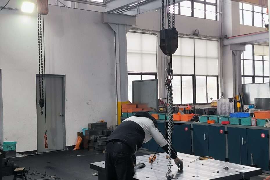
If you are a product designer whose parts have always been made by injection molding, stamping, or machining, and now someone says “we should make this in SMC,” this guide is for you. SMC (Sheet Molding Compound) compression molding uses fundamentally different tooling than injection molding, with different design rules, cost drivers, and failure modes. Understanding the mold is the first step to designing parts that mold well.
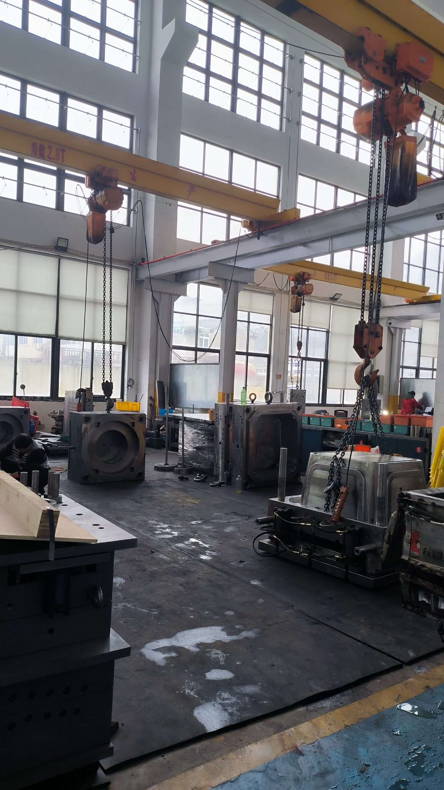
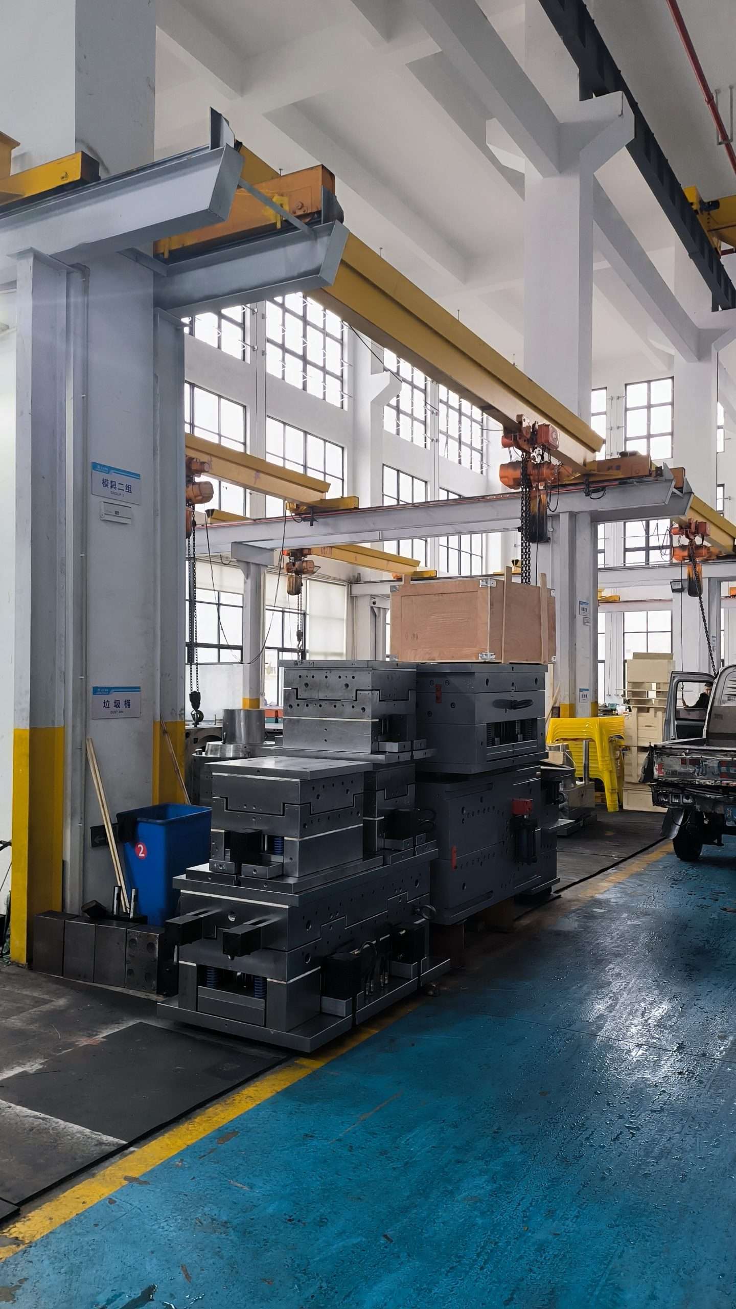

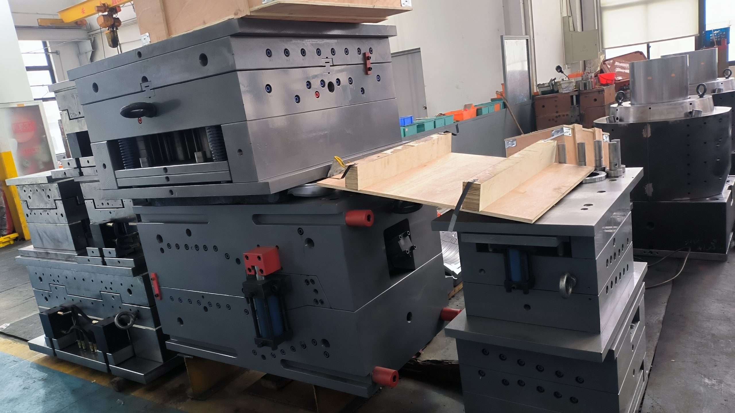
What Exactly Is an SMC Mold? A Simple Explanation
An SMC compression mold is a matched-metal tool consisting of two halves: a cavity (female side, typically the bottom) and a core (male side, typically the top). The mold is mounted in a hydraulic press that provides 500–2,000 tons of clamping force. A pre-weighed charge of SMC — a dough-like sheet of glass fiber-reinforced polyester resin — is placed in the heated mold at 140–160°C. The press closes, the SMC flows under pressure to fill the cavity, and the heat cures the resin in 2–5 minutes. The press opens, ejector pins push the part out, and the cycle repeats. Unlike injection molding, the material flows only a short distance (typically 100–400 mm from the charge placement area), and the mold must be designed to vent trapped air as the material flows.
Why SMC Mold Design Matters
The mold determines everything about the final part: surface finish, dimensional accuracy, cycle time, and defect rate. A well-designed SMC mold produces parts that require minimal deflashing and zero rework. A poorly designed mold produces flash (excess material at the parting line), porosity (trapped air bubbles on the surface), warpage (uneven shrinkage), and sticking (parts that will not release). Each of these defects has a mold-design root cause that can be prevented — but once the mold is cut from hardened steel, fixing these problems is expensive and slow.
The Basic Types of SMC Molds
SMC molds are classified by production volume. Prototype molds use P20 pre-hardened tool steel (28–32 HRC) and are designed for 5,000–20,000 cycles — suitable for development programs and low-volume production. Production molds use H13 hot work tool steel (46–50 HRC after heat treatment) and are designed for 50,000–150,000 cycles. High-volume production molds add hard chrome plating (65–70 HRC surface hardness) for 150,000–300,000+ cycle life. Single-cavity molds produce one part per cycle. Multi-cavity molds (2, 4, or more cavities) multiply throughput — a two-cavity mold running 3-minute cycles produces 40 parts per hour versus 20 for a single-cavity mold, with a mold cost increase of roughly 60–80% rather than 100%.
How an SMC Mold Is Made
SMC mold manufacturing begins with a 3D CAD model of the part. The mold designer adds: parting line (where the two mold halves separate), shear edge (the vertical land that controls flash and builds back-pressure for cavity filling), draft angles (typically 1–3° on vertical walls for part release), ejector pin locations, heater cartridge bores, thermocouple wells, and vent grooves. The mold steel is rough-machined on a CNC mill, heat-treated (for H13), finish-machined, and then polished — progressively finer abrasives from 120-grit stones down to 1-micron diamond paste for mirror finishes. Chrome plating, if specified, is applied to the finished cavity surface. The completed mold is mounted in a tryout press, sample parts are molded, and dimensions are verified on a CMM.
What to Look For When Ordering an SMC Mold
When specifying an SMC mold, confirm: (1) The mold steel grade and hardness — P20 is adequate for under 20,000 cycles; H13 with chrome plating for production volumes. (2) Replaceable shear edge inserts — the shear edge wears fastest; it should be a separate insert that can be replaced without re-machining the cavity. (3) Temperature control — cartridge heaters with thermocouples in each heating zone, positioned for ±3°C uniformity at the cavity surface. (4) Venting — dedicated vent grooves at the last areas to fill; do not rely on shear edge clearance alone. (5) Ejector system — pins distributed on flat surfaces, sized for 150% of calculated ejection force. (6) Tryout — the mold should be trialed with your SMC material, not the mold shop’s generic material.
Common Beginner Mistakes in SMD Mold Design
Mistake #1: Insufficient draft angle. SMC parts shrink onto the core during cooling. Vertical walls with less than 1° draft can require ejection forces that damage the part. Minimum 1.5° draft on all vertical surfaces, 3° on textured surfaces. Mistake #2: Sharp internal corners. SMC does not flow into sharp corners — minimum 1.5 mm internal radius. Sharp corners also create stress concentrations in the mold steel. Mistake #3: Uneven wall thickness. SMC flows preferentially through thick sections, potentially short-filling thin sections. Maintain uniform wall thickness within ±20%. Mistake #4: Placing ribs on the wrong side of the part. Ribs should be on the core side, not the cavity side, so that part shrinkage helps release the ribs rather than gripping them tighter. Mistake #5: Not designing for part shrinkage — SMC parts shrink 0.1–0.3% during cure; the mold cavity must be sized to compensate.
SMC Mold Steel Selection Guide
| Steel Grade | Hardness | Cycles Expected | Best For | Cost Index |
|---|---|---|---|---|
| P20 | 28–32 HRC | 5K–20K | Prototypes, low volume | 1.0× |
| H13 | 46–50 HRC | 50K–150K | Production, medium volume | 1.8× |
| H13 + Chrome Plate | 65–70 HRC (surface) | 150K–300K+ | High volume, Class A surface | 2.3× |
| 420SS (Stainless) | 48–52 HRC | 30K–80K | Corrosive SMC formulations | 2.5× |
TSTAR Mold designs and builds SMC compression molds from prototype to production volume. In-house CNC machining, EDM, polishing, and chrome plating. Our engineers work with product designers to optimize part geometry for moldability before steel is cut. Contact us with your part concept for a design-for-manufacturing review.