
A mold maker in Huangyan spent three weeks tweaking an SMC automotive bracket mold because parts kept sticking in the cavity. He tried increasing draft angle. He tried mold release. He tried slowing down the press. Nothing worked until he pulled the ejector layout drawing and realized the problem wasn’t release — it was that four ejector pins were pushing on unsupported thin sections, flexing the part instead of pushing it off the core.
Ejector design for SMC molds doesn’t get the attention that heating or shear edge design does. It should. A bad ejector layout turns a mold that should run 300,000 cycles into one that needs rework at 5,000. Here’s how to get it right the first time.
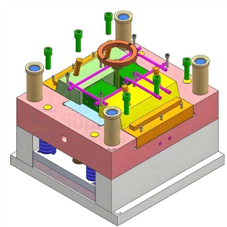
What’s Different About SMC Ejection vs Injection Molding
If you’ve designed ejector systems for thermoplastic injection molds, forget most of what you know. SMC ejection is a different animal.
SMC parts are stiffer at demolding temperature. Thermoplastic parts come out hot and somewhat flexible — you can bend them off the core to some degree. SMC parts cure in the mold at 140–160°C and are already fully crosslinked at demolding. They’re rigid. If an ejector pushes on the wrong spot, the part doesn’t flex — it cracks or the boss shears off.
SMC shrinks less and differently. Thermoplastic parts shrink 0.5–2.0% as they cool, which naturally pulls them away from the cavity and onto the core — that’s why you put ejectors on the core side. SMC shrinkage is 0.05–0.3%, and it’s mostly chemical shrinkage during cure, not thermal. The part doesn’t “grab” the core the same way. Sometimes it sticks to the cavity instead, which means you need ejectors on both sides.
There’s no “ejector pin mark is OK” mentality. SMC parts go into visible automotive and electrical applications. Pin marks on a Class A surface are a reject. Injection molding can hide pin marks on the B-side. SMC parts are often thinner (2–4mm) and the B-side might still be visible in the assembled product. Pin placement matters more.
Step 1: Calculate Ejection Force
You need to know how much force it takes to push the part off before you can size pins. The basic formula:
F = μ × A × P
Where:
– F = ejection force (N)
– μ = coefficient of friction between part and mold steel (typically 0.15–0.35 for SMC on P20 steel)
– A = contact area between part and mold surface (mm²)
– P = contact pressure from shrinkage (typically 0.5–2.0 MPa for SMC)
A hood-sized SMC part with 0.3 m² of core contact area and μ=0.25 needs roughly 37.5–150 kN of ejection force depending on shrinkage pressure. That’s 8–30 ejector pins at 5 kN per pin. Don’t guess — do the math.
The friction coefficient isn’t constant. It changes over the mold’s life as the tool surface wears and as mold release builds up. New tools eject easier (μ≈0.15). Well-used tools with micro-scratches eject harder (μ≈0.30+). Design for the high end or you’ll regret it at 50,000 cycles.
Step 2: Pick Ejector Type
Four ejector types cover most SMC applications:
Round ejector pins — the default. Diameters from 4mm to 25mm. For SMC, stay above 8mm diameter. Anything smaller bends under the ejection load or punches through the part. Hardened H13 steel, nitrided surface. The pin-to-bore clearance should be 0.01–0.02mm — any looser and SMC flash will pack the gap and seize the pin.
Blade ejectors — for ribs and thin walls. Rectangular cross-section, used when a round pin won’t fit. SMC rib sections are often 2–3mm wide. A 1.5mm blade ejector can work, but it’s fragile. Use D2 tool steel at HRC 58–60 for blades under 2mm. Anything thinner than 1.2mm is asking for trouble.
Stripper plates — for large flat areas. A stripper plate pushes on the entire perimeter of the part. This distributes ejection force uniformly and eliminates pin marks entirely. The trade-off: stripper plates add $3,000–8,000 to tooling cost and need guide bushings and limit switches. For cosmetic SMC parts where pin marks are unacceptable, it’s the right solution.
Lifter pins with hydraulic assist — for undercuts. SMC parts with snap-fit features or undercuts need lifters that move laterally during ejection. The difference from injection molding: SMC has near-zero elasticity after cure, so the lifter needs to clear the undercut completely, not just flex the part past it.
Step 3: Place Ejectors Where They Actually Help
Pin placement matters more than pin count. An SMC mold with 20 poorly-placed ejectors performs worse than one with 12 well-placed ones.
Push on ribs and bosses, not on flat fields. The stiffest features of an SMC part are ribs, bosses, and wall intersections. That’s where ejection force transfers best. A pin pushing on a 2.5mm flat panel will flex the panel. The same pin pushing on a 3mm rib at the base of that panel will push the entire part.
Balance ejection force around the part center of gravity. If all your ejectors are on one side, the part cocks during ejection and binds on the core. The result: one corner comes free while the opposite corner stays stuck. Distribute ejectors so the resultant ejection force passes within 20mm of the part’s center of area.
Double up near vertical walls. The highest sticking force is always near vertical walls and deep ribs — these have the most contact area per unit of projected area. Put ejectors within 10–15mm of vertical walls. Don’t put them right at the wall base (the steel section becomes too thin) but get close.
Avoid push-on-thin-sections. If the part thickness at the ejector location is under 2mm, the pin will punch through or leave a visible mark on the opposite surface. Add a local pad — a 1mm thicker area at the ejector location — to distribute the load. This adds barely any material and prevents a lot of scrap.
Step 4: Set Stroke Length and Timing
Ejector stroke needs to clear the tallest feature on the core. For SMC molds, that’s typically 10–25mm for flat parts and 30–60mm for parts with deep ribs. Add 5mm of safety margin.
Timing matters too. If the press opens and the ejectors fire while the part is still hot (above 80°C), the part is slightly more flexible and ejects easier. If the press waits and the part cools, it’s stiffer and harder to eject. Most SMC lines eject at 80–100°C part temperature — hot enough to help ejection, cool enough that the part won’t deform under its own weight.
Common Ejector Problems and Fixes
| Problem | Likely Cause | Fix |
|---|---|---|
| Part sticks to cavity (not core) | Insufficient draft on cavity side; cavity surface too polished | Add 1–2° draft to cavity verticals; reduce cavity surface polish to SPI B-2 to increase grip on core side |
| Pin punches through part | Pin too small for load; part too thin at pin location | Increase pin diameter to 8mm minimum; add local pad-up to 3mm thickness at pin location |
| Pin bends after 5,000–10,000 cycles | Undersized pin; misaligned ejector plate | Upgrade to larger diameter or H13 with nitriding; check ejector plate parallelism |
| Flash packs ejector pin bore | Excessive pin-to-bore clearance; low-viscosity SMC | Tighten clearance to 0.01–0.02mm; add flash trap groove around pin |
| Part cocks and binds during ejection | Unbalanced ejector layout | Redistribute pins to balance forces around part center of area |
| Pin marks visible on A-surface | Pin too close to A-surface; insufficient pad thickness | Move pin to B-surface feature (rib/boss); add 1mm local pad if relocation isn’t possible |
FAQ
How many ejector pins does a typical SMC mold need?
A hood-sized mold (0.3–0.5 m² projected area) typically uses 12–20 ejector pins. A smaller electrical enclosure mold uses 6–12. More pins isn’t better — each pin is a potential flash path and a maintenance point. Calculate the force, then use the minimum number of properly-sized pins to deliver it.
Should I use ejector sleeves on SMC mold cores?
Ejector sleeves around core pins work — they’re standard on bosses and mounting holes. But the sleeve wall needs to be at least 1.5mm thick for SMC ejection forces. Thinner sleeves will crack at the shoulder. If your boss is too small for a 1.5mm sleeve wall, use a stripper plate or redesign the boss.
Do I need ejectors on both mold halves?
For simple geometries with 3°+ draft on all surfaces — probably not. For complex parts with undercuts, zero-draft surfaces, or textures on both sides — yes. SMC’s low shrinkage means you can’t count on the part naturally staying on one side. If you’re unsure, put two small ejectors on the cavity side as insurance. Adding them to an existing mold costs 10× what putting them in the original design would.
What about vacuum-assisted ejection?
Some SMC molds use vacuum cups on the end-of-arm tooling rather than mechanical ejectors in the mold. This works for large flat parts where the robot can get a good grip. It eliminates pin marks entirely. The downside: it’s slower (the robot has to enter the press, grip, and retract) and doesn’t work for parts with irregular A-surfaces where cup placement is limited.