
The gate is the smallest cross-section in an injection mold’s feed system — and also the most consequential. A poorly placed or undersized gate produces weld lines, jetting, sink marks, and burn marks that no amount of process adjustment can fix. A correctly designed gate, by contrast, fills the cavity evenly, packs the part uniformly, and leaves a vestige so small that the customer never notices. This article covers the six most common gate types, the physics that govern gate sizing, and a step-by-step selection framework that works across thermoplastic, thermoset, and elastomer molding.
Gate Fundamentals: Pressure Drop, Shear Rate, and Freeze-Off
Three physical phenomena govern gate performance. First, pressure drop across the gate — smaller gates generate higher shear rates, which aid thin-wall filling but increase the required injection pressure. Second, shear heating — polymer flowing through a restricted gate experiences a temperature rise of 10-30°C from viscous dissipation, which temporarily lowers viscosity and improves flow. Third, gate freeze-off — the gate must remain molten long enough to transmit holding pressure for packing, then freeze before the screw retracts to prevent backflow.
The gate freeze time for a circular gate can be approximated by: t_freeze ≈ (d² / (π² × α)) × ln[(4/π) × (T_melt – T_mold) / (T_eject – T_mold)], where d is gate diameter, α is thermal diffusivity (~0.08 mm²/s for most thermoplastics), T_melt is melt temperature, T_mold is mold wall temperature, and T_eject is the no-flow temperature. For a 1.5 mm diameter gate processing ABS at 230°C melt and 50°C mold temperature, the freeze time is approximately 2-3 seconds.
| Gate Type | Typical Size Range | Pressure Drop | Vestige Quality | Best For |
|---|---|---|---|---|
| Edge/Sprue Gate | 0.8-3.0 mm dia | Low | Poor (manual trim) | Large parts, thick walls |
| Pin/Submarine Gate | 0.5-1.5 mm dia | Moderate | Good (auto-shear) | Multi-cavity, automated |
| Fan Gate | 0.5-2.0 mm thick | Low | Fair | Flat parts, optical |
| Diaphragm Gate | 0.5-1.5 mm thick | Low | Moderate | Cylindrical, concentric |
| Hot Tip (Valve) | 0.8-3.0 mm dia | Very low | Excellent | High-cosmetic, high-volume |
| Cashew/Banana Gate | 0.5-1.5 mm dia | Moderate | Excellent (hidden) | Cosmetic surfaces |
Edge Gate: The Workhorse for Large Parts
Edge gates feed the cavity from the parting line, entering the part at its perimeter. They’re the simplest gate to machine and the most forgiving for process window width. The gate land — the short parallel section before the cavity — should be 0.5-1.0 mm long to prevent gate blush while providing a clean break point.
Edge gate sizing follows a straightforward rule: gate depth = 0.5-0.8 × part wall thickness at the gate location. For a 3 mm wall thickness, start with a 1.5-2.0 mm deep gate. Gate width should be 1.5-3.0 times the depth for adequate flow. The primary limitation of edge gates is the manual degating step — molded-in stress around the gate vestige can cause cracking if the operator twists rather than shears the sprue. Automated hot-knife degating improves consistency but adds cycle time.
Pin and Submarine Gates: Automated Degating
Pin gates (also called tunnel or submarine gates) enter the cavity through an angled channel machined into one mold half. When the mold opens or the part ejects, the gate shears automatically at the cavity wall, leaving a small witness mark. The gate angle is critical: 30-45° from the parting plane for standard submarine gates, and 40-60° for banana/cashew gates that enter from the non-appearance side.
Pin gate diameter for common thermoplastics follows the formula: d = C × (W_fill)^(1/3), where W_fill is the shot weight in grams and C is a material constant (0.6 for PE/PP, 0.7 for ABS/PS, 0.8 for PC, 0.9 for POM, 1.0 for PA). For a 50 g ABS shot: d ≈ 0.7 × (50)^(1/3) ≈ 2.6 mm. This empirical formula provides a safe starting point that balances pressure drop against freeze-off time.

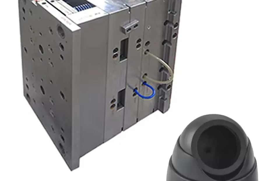
Gate Placement: The Five Rules
Gate location determines flow pattern, and flow pattern determines part quality. Five rules govern placement:
1. Gate into the thickest section. Polymer flows from thick to thin — not the reverse. Gating into a thin section forces the melt to try filling a thicker section downstream, creating hesitation marks and poor packing. Always position the gate at the heaviest wall section and let the flow front advance into progressively thinner regions.
2. Avoid gating directly opposite cores or pins. The melt stream splitting around a core creates a weld line on the downstream side. If unavoidable, position the gate so the weld line forms in a low-stress, non-cosmetic area — and use a wider gate to reduce the temperature drop across the parting flow.
3. Gate-to-flow-length ratio (L/t rule). For most unfilled thermoplastics, the maximum flow length from gate to furthest cavity extremity should not exceed 150-200 times the wall thickness. A 2 mm wall ABS part has a practical fill limit of 300-400 mm from a single gate. Glass-filled grades reduce this to 80-120:1 because of higher melt viscosity.
4. Consider gate vestige location on the finished part. For consumer-facing surfaces (Class A), specify a submarine gate entering from the B-side, or a valve-gated hot runner. The cost increment for a hot tip — approximately $1,500-3,000 per nozzle — is often justified by eliminating secondary deflashing operations on high-volume cosmetic parts.
5. Balance filling across multi-cavity molds. In a multi-cavity tool, all cavities should fill simultaneously. The runner system should be designed with equal flow lengths (naturally balanced layout) rather than relying on artificially balanced runners that work only at one set of process conditions. For 4+ cavity tools, a radial or H-pattern runner layout ensures uniform cavity-to-cavity fill.
Gate Sizing Reference Table by Material
| Material | Edge Gate Depth (mm) | Pin Gate Dia (mm) | Max L/t Ratio | Shear Rate Limit (1/s) |
|---|---|---|---|---|
| PP (unfilled) | 0.8-2.5 | 0.6-2.0 | 250:1 | 100,000 |
| ABS | 1.0-2.5 | 0.8-2.0 | 200:1 | 50,000 |
| PC | 1.5-3.0 | 0.8-2.5 | 100:1 | 40,000 |
| PA66 (unfilled) | 1.0-2.5 | 0.5-1.8 | 200:1 | 60,000 |
| POM | 1.0-2.5 | 0.8-2.0 | 150:1 | 40,000 |
| PP+30% GF | 1.5-3.0 | 1.0-2.5 | 100:1 | 30,000 |
| PA66+30% GF | 1.5-3.0 | 1.0-2.5 | 80:1 | 25,000 |
| PC/ABS blend | 1.2-2.5 | 0.8-2.0 | 150:1 | 40,000 |
Frequently Asked Questions
How do I choose between a cold runner and hot runner gate system?
The breakeven analysis is straightforward: hot runners eliminate runner regrind and reduce cycle time (no runner cooling), but add $1,500-3,000 per nozzle in tooling cost. For high-volume production (>100,000 shots/year) with expensive engineering resins, hot runners pay back in 6-12 months. For short runs or commodity resins (PP, PE), cold runners with edge or submarine gates are more cost-effective. Valve-gated hot tips add approximately $500-800 per gate over open hot tips but eliminate gate vestige and stringing on the part surface.
Why do my parts have jetting marks from the gate?
Jetting occurs when the melt stream shoots through the gate as a high-velocity jet rather than expanding smoothly into the cavity. Three causes: (1) gate too small for the fill rate, creating excessive shear velocity; (2) gate land too short, preventing the melt from establishing a fountain-flow front; (3) gate impinging on a cavity wall too close to the gate exit. Increase gate size, lengthen the gate land to 1.0-1.5 mm, or position a core pin directly opposite the gate to break up the jet.
What is the smallest practical gate diameter?
For unfilled thermoplastics, 0.5 mm is the practical minimum for a pin gate — below this, shear heating degrades the polymer before filling completes. For LSR (liquid silicone rubber), gates as small as 0.1-0.2 mm are possible because of the material’s low viscosity. The trade-off with very small gates is higher injection pressure requirement and narrower process window for freeze-off timing.
Can I change gate size without modifying the mold?
Only with hot runner systems that have interchangeable gate inserts. On cold runner molds, gate dimensions are machined directly into the steel — increasing gate size requires additional machining, while reducing it typically requires welding and re-machining or an insert. This is why conservative gate sizing with the option to open up later is standard mold design practice: start 10-15% undersized and open up if fill or packing issues arise.
For a more detailed look at mold steel selection for gate and runner systems, see our mold steel selection guide.
For industry-standard gate design guidelines and mold-making specifications, refer to the Society of Plastics Engineers (SPE) Mold Technologies Division.
Standards & References
The following industry standards are referenced in this article: