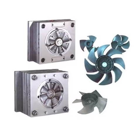
An injection mold cavity spends roughly 70–80% of the cycle time under cooling. For a typical 20-second cycle, that means 14–16 seconds are wasted if the cooling system is poorly designed. A 1-second reduction in cycle time at a production volume of 500,000 parts per year translates to approximately 7,000 hours of saved machine time. The cooling system is not a plumbing accessory bolted onto the mold — it is the single largest lever for productivity in injection molding.
Despite this, many mold designs treat cooling channels as an afterthought. Straight-drilled lines through the cavity plate, uneven spacing around core features, and unregulated water flow are common shortcuts that extend cycles, induce warpage, and scrap parts. This article provides quantitative guidelines for cooling channel geometry, layout, and simulation that apply to production tooling.
Cooling Channel Sizing: Diameter, Spacing, and Distance to Cavity
Three parameters define a cooling channel layout: channel diameter (d), center-to-center spacing (p), and the distance from the channel centerline to the cavity wall (h). These values determine the heat transfer rate and the uniformity of the mold surface temperature.
The recommended starting point for steel molds processing engineering thermoplastics is d = 10–12 mm, p = 25–35 mm, and h = 15–20 mm. The spacing-to-diameter ratio (p/d) should stay between 2.5 and 3.0. At p/d = 2.5 (e.g., p = 25 mm, d = 10 mm), the temperature variation across the mold surface is ±3°C. At p/d = 4.0, that variation widens to ±8°C — enough to cause visible sink marks on Class A surfaces.
The distance h is the most commonly violated parameter. A channel placed 25 mm from the cavity wall instead of 15 mm reduces the heat flux by roughly 40%. For deep cavities where core pins and ejectors compete for space, the minimum viable h is 8 mm — below that, the structural integrity of the steel between the channel and the cavity is compromised under 1000+ bar injection pressure.
These relationships hold for P20 and H13 tool steels. For aluminum mold inserts (which are sometimes used for prototype or low-volume runs), thermal conductivity is roughly 5× higher than steel, allowing wider spacing — but the channel-to-cavity distance should still be kept under 12 mm to take advantage of the conductivity.
Flow Regime and Cooling Channel Circuit Design
The cooling efficiency of any channel depends on the flow regime inside it. Turbulent flow (Reynolds number Re ≥ 4000) transfers heat 3–5× more effectively than laminar flow. For a 10 mm diameter channel, achieving Re = 4000 with water at 20°C requires a flow velocity of approximately 0.4 m/s, or a volumetric flow rate of about 1.9 L/min per circuit.
In practice, most mold temperature controllers deliver 5–15 L/min total. If a mold has eight independent circuits, each circuit receives 0.6–1.9 L/min — barely enough for turbulent flow in one or two circuits. The rest operate in laminar or transitional flow, wasting their heat transfer potential. This mismatch between pump capacity and circuit count is the single most common cause of poor cooling performance in production molds.
Circuit layout strategy follows a simple hierarchy: connect channels in series-parallel combinations so that each circuit balances pressure drop within ±10%. A circuit longer than 2 meters (total flow path through the mold) loses 0.5–1.0 bar pressure per meter at 0.5 m/s velocity, which may exceed the available pump pressure if combined with other restrictions.
| Parameter | Optimal Range | Impact of Deviation |
|---|---|---|
| Channel diameter (d) | 10–12 mm | < d = high pressure drop; > d = reduced steel support |
| Spacing (p) | 2.5–3.0 × d | > 3× d = uneven cooling (±8°C) |
| Distance to cavity (h) | 15–20 mm | > 25 mm = 40% heat flux reduction |
| Flow velocity | ≥ 0.4 m/s | < 0.4 m/s = laminar flow, low heat transfer |
| Circuit length | ≤ 2 m per circuit | > 2 m = excessive pressure drop |
| Reynolds number | ≥ 4000 | < 4000 = 3–5× lower heat transfer |
| Pressure drop per circuit | ≤ 1.5 bar | > 1.5 bar = flow imbalance between circuits |
Conformal Cooling: When Straight Drilled Channels Are Not Enough
Straight drilled channels cannot follow the contour of a complex core geometry. The distance h varies between the channel and different cavity surfaces, producing temperature gradients that cause differential shrinkage and warpage. Conformal cooling — channels that follow the cavity surface at a constant distance — eliminates this variation.
Additive manufacturing (laser powder bed fusion or binder jetting) now makes conformal cooling inserts viable for production tooling. A study published in the Journal of Materials Processing Technology (Park et al., 2022) measured a 35% reduction in cycle time for a conformally cooled automotive connector mold compared with the conventional straight-drilled equivalent. The conformal insert cost roughly 2.5× more than a machined equivalent, yielding a payback period of 3–4 months at 24/7 production.
Conformal cooling is most justified when: (1) the part has deep cores, ribs, or bosses that produce thermal hot spots with straight channels; (2) the annual production volume exceeds 200,000 parts; (3) the part material has a narrow processing window (e.g., polycarbonate or LCP); and (4) the mold steel is compatible with additive manufacturing (maraging steel or stainless steel 316L).
Cooling Channel Gallery

Frequently Asked Questions
What is the minimum cooling channel diameter for production molds?
8 mm is the practical minimum. Below 8 mm, pressure drop increases sharply — a 6 mm channel produces roughly 4× the pressure drop of an 8 mm channel at the same flow rate, and particles in the cooling water (scale, rust, debris) block 6 mm channels far more frequently.
How do I check whether my cooling channels are turbulent or laminar?
Calculate the Reynolds number using Re = (ρ × v × d) / μ, where ρ is water density (998 kg/m³ at 20°C), v is flow velocity in m/s, d is channel diameter in meters, and μ is dynamic viscosity (1.002 × 10⁻³ Pa·s). Insert a flow meter and a thermometer at the supply line. If Re < 4000, increase pump speed or reduce the number of parallel circuits to raise velocity per circuit.
Is conformal cooling always better than straight drilled channels?
No. Conformal cooling is justified when the mold has core geometries that straight channels cannot follow within 20 mm of the cavity surface. For flat, simple geometries like a rectangular box or flat panel, conventional channels with correct spacing achieve the same performance at lower cost. Conformal cooling excels on deep-draw parts, complex core geometries, and parts with tight dimensional tolerances (CT3 or tighter).
What coolant temperature should I use for ABS, polycarbonate, and nylon?
ABS: 40–60°C mold surface → use coolant at 30–50°C. Polycarbonate: 80–100°C mold surface → coolant at 70–90°C (often requires an oil-based temperature controller). Nylon (PA6/PA66): 60–90°C mold surface → coolant at 50–80°C. Using coolant below the recommended range causes premature freeze-off at the gate and incomplete packing, especially on thin-wall sections.
How many cooling circuits should a mold have?
As a rule of thumb, one circuit per 300–400 mm of projected cavity length. For a 400 × 300 mm rectangular cavity, this means 2–3 independent circuits per mold half. Each circuit should serve a zone of similar cooling demand — the gate area, for example, often requires a separate circuit with warmer coolant to prevent early gate freeze-off.
Can I use aluminum instead of steel to improve cooling?
Aluminum inserts (7075-T6 or QC-10) offer 3–5× higher thermal conductivity than P20 steel, but their surface hardness and wear resistance are lower. They work for prototype or low-volume production (under 50,000 cycles) and significantly reduce cooling time. For high-volume production, use steel with well-designed channels rather than aluminum — the aluminum advantage disappears if the channels are poorly positioned.
What causes uneven cooling between cavity and core halves?
The core typically runs hotter because it is surrounded by melt on three sides, while the cavity has a steel backing plate acting as a heat sink. Differential cooling produces parts that bow toward the colder side. The fix is to adjust coolant flow and temperature independently for each half — the core should receive coolant at 5–10°C lower temperature and/or 15–20% higher flow rate than the cavity.
For a broader overview of injection mold design principles, see our Injection Mold Design Guide. For mold steel selection suited to cooling channel layouts, refer to the Mold Steel Selection Guide.
Industry-standard cooling design references include the Society of Plastics Engineers (SPE) Mold Making and Mold Design Division and the VDI 2006 standard for mold temperature control.
Standards & References
The following industry standards are referenced in this article: