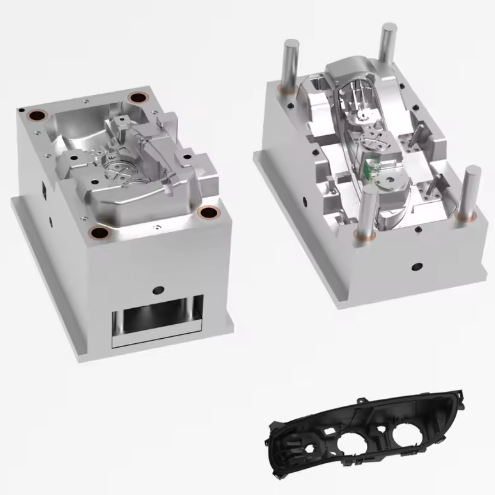
The headlight cover mold represents a critical component in automotive lighting systems, demanding exceptional precision to ensure optimal light transmission, impact resistance, and long-term durability. Modern headlight cover molds must achieve optical clarity (transmittance ≥90%), dimensional accuracy (±0.03mm for critical features), and surface finish (Ra ≤0.025μm) while withstanding operating temperatures from -40°C to 120°C. This comprehensive guide explores material selection, design considerations, manufacturing processes, and quality control standards specific to headlight cover mold applications, providing engineers with the technical framework for producing high-performance automotive lighting components.
2. Material Selection for Headlight Cover Molds
2.1 Pre-hardened Mirror Steel 718H
718H stands as the benchmark material for headlight cover molds requiring high precision and extended production runs. This pre-hardened steel (35-40 HRC) offers exceptional polishability, reaching SPI A-2 surface finish (Ra 0.025-0.05μm) with minimal effort. The material’s nickel-enriched composition (1.0-1.5% Ni) enhances dimensional stability, maintaining tight tolerances during prolonged production cycles. Headlight cover molds fabricated from 718H typically achieve 500,000-800,000 cycles before requiring maintenance, making it ideal for mid-to-high volume production of complex headlight geometries.
2.2 Corrosion-Resistant Stainless Steel S136
For headlight cover molds processing polycarbonate (PC) with UV stabilizers or other corrosive additives, S136 stainless steel provides superior performance. This material offers exceptional corrosion resistance (500-hour salt spray resistance per ASTM B117) and maintains mirror polish (Ra ≤0.012μm) even after 1 million cycles. S136’s low carbon content (0.38%) minimizes carbide precipitation during heat treatment, ensuring uniform hardness distribution (48-52 HRC) across the headlight cover mold cavity. The material’s thermal conductivity (16 W/(m·K)) requires specialized cooling system design, but this limitation is offset by its ability to maintain optical clarity in chemically aggressive environments.
2.3 Age-Hardening Mirror Steel NAK80
NAK80 has emerged as the material of choice for headlight cover molds demanding Class A surfaces without secondary polishing. This pre-hardened steel (37-43 HRC) features aluminum addition (0.7-1.0%) that forms fine precipitates during aging, enabling direct diamond cutting to SPI A-1 finish (Ra 0.012-0.025μm). The material’s exceptional machinability reduces headlight cover mold production time by 20-30% compared to conventional steels. NAK80’s dimensional stability (±0.02mm/m) is particularly valuable for headlight cover molds with complex optical features, ensuring consistent light refraction characteristics across production batches.
2.4 High-Temperature Resistant Steel CH302
For headlight cover molds processing BMC (Bulk Molding Compound) materials, CH302 offers superior thermal stability at operating temperatures up to 160°C. This chromium-molybdenum alloy steel (52-55 HRC) maintains hardness and wear resistance under prolonged thermal cycling, extending headlight cover mold life beyond 1 million cycles. The material’s high thermal conductivity (35 W/(m·K)) facilitates uniform heat distribution, critical for preventing premature curing of BMC materials during injection molding. CH302’s resistance to thermal fatigue makes it ideal for headlight cover molds incorporating intricate cooling channels for complex lens geometries.
3. Design Considerations for Headlight Cover Molds
3.1 Optical Surface Requirements
The headlight cover mold must achieve precise surface characteristics to ensure optimal light transmission:
- Surface finish: SPI A-1 standard (Ra 0.012-0.025μm) across all optical surfaces
- Form accuracy: ±0.005mm for critical lens curvature
- Texture uniformity: Maximum variation of 5% in surface roughness measurements
- Edge definition: Radius ≤0.05mm for light guide features
These requirements demand specialized polishing techniques, including diamond paste finishing (3-6μm grit) followed by electrolytic polishing to remove subsurface damage. The headlight cover mold’s optical performance directly impacts vehicle safety, as even minor surface irregularities can cause light scattering and reduced road illumination.
3.2 Hot Runner System Design
Advanced headlight cover molds utilize sophisticated hot runner systems to ensure uniform filling and minimize optical defects:
- Nozzle configuration: 5-point sequential valve gate system (Flexflow technology)
- Temperature control: ±1°C accuracy with individual zone monitoring
- Gate design: Fan-shaped edge gates (1.2mm×8mm) to eliminate weld lines
- Pressure control: 104-143 MPa injection pressure with 3-stage profiling
The sequential valve gating allows precise control of melt flow front advancement, critical for maintaining the optical integrity of headlight cover mold components. This system reduces pressure drop by 30% compared to conventional hot runners, minimizing shear-induced molecular orientation in PC materials.
3.3 Cooling System Optimization
Efficient thermal management is essential for headlight cover mold performance:
- Channel layout: Conformal cooling with 15-20mm spacing from cavity surface
- Diameter specification: 8mm main channels with 6mm branch lines
- Temperature differential: ≤5°C between inlet and outlet
- Heat extraction capacity: ≥1500 kJ per molding cycle
For complex headlight cover mold geometries, 3D-printed conformal cooling inserts can reduce cycle time by 25-35% while improving part consistency. The cooling system must maintain mold temperature within ±2°C across all optical surfaces to prevent residual stress-induced birefringence in the final headlight cover.
3.4 Ejection System Design
The headlight cover mold’s ejection system requires careful engineering to prevent surface damage:
- Ejection method: Hydraulic lifters with sequential actuation
- Contact area: ≥15% of part surface to distribute forces evenly
- Ejection speed: 50-80mm/s with velocity profiling
- Return accuracy: ±0.01mm to ensure proper cavity closure
Non-contact ejection methods, such as air blasts, are often employed for critical optical surfaces. The headlight cover mold’s ejection sequence must be synchronized with cooling to prevent premature deformation of the PC component during demolding.
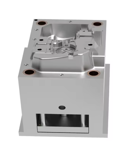
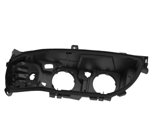
4. Manufacturing Processes for Headlight Cover Molds
4.1 Precision Machining
Headlight cover mold manufacturing demands state-of-the-art machining capabilities:
- 5-axis milling: ±0.002mm positioning accuracy for complex optical surfaces
- EDM wire cutting: 0.001mm resolution for intricate cooling channels
- Micro-machining: 10μm precision for light guide features
- Laser texturing: 5-50μm depth control for anti-glare surfaces
The machining process for headlight cover molds typically involves multiple steps, starting with roughing operations using carbide end mills, followed by semi-finishing with ceramic tools, and concluding with high-speed finishing using diamond-coated cutters. Each machining operation must be followed by rigorous inspection to ensure the headlight cover mold meets the stringent optical requirements.
4.2 Surface Treatment
Headlight cover mold surfaces require specialized treatments to achieve optical performance:
- Diamond polishing: 3μm to 0.5μm grit sequence for SPI A-1 finish
- Electrolytic polishing: 10-15V DC for 20-30 seconds to remove micro-scratches
- Nitriding: 0.1-0.2mm case depth with 800-1000 HV surface hardness
- Chrome plating: 5-10μm thickness for corrosion resistance (optional)
The polishing process for headlight cover molds is particularly critical, as any surface irregularity can degrade optical performance. Automated polishing systems with force feedback are increasingly employed to ensure consistency across large headlight cover mold surfaces.
4.3 Assembly and Alignment
Headlight cover mold assembly requires sub-micron precision to maintain optical integrity:
- Guide pillar alignment: ±0.005mm parallelism over full stroke
- Plate parallelism: ≤0.01mm/m across parting surfaces
- Hot runner concentricity: ±0.01mm between nozzle and gate
- Sensor integration: Temperature monitoring at 12 critical locations
The assembly process for headlight cover molds typically involves laser alignment and coordinate measuring machine (CMM) verification at each stage. This ensures that the final headlight cover mold maintains its precision under production conditions, including thermal expansion and clamping forces.
5. Process Parameters for Headlight Cover Molds
5.1 Polycarbonate (PC) Processing
Optimal parameters for PC headlight cover molding include:
- Melt temperature: 280-300°C (zone temperature profiling)
- Mold temperature: 120-140°C (using high-temperature oil heating)
- Injection pressure: 90-110 MPa (with 3-stage pressure profile)
- Cooling time: 35-45 seconds (depending on wall thickness)
- Post-molding annealing: 120°C for 2 hours to relieve stress
These parameters balance production efficiency with part quality, ensuring the headlight cover mold produces components with minimal residual stress and optimal light transmission. The injection speed profile is particularly critical, with typical velocities ranging from 50-100mm/s to minimize shear stress in the PC material.
5.2 BMC Material Processing
When molding BMC headlight components:
- Mold temperature: 150-160°C (electric cartridge heaters)
- Injection pressure: 70-90 MPa
- Cure time: 60-90 seconds (depending on part thickness)
- Post-curing: 150°C for 2 hours to complete polymerization
The headlight cover mold must maintain precise temperature control for BMC processing, as insufficient heat can result in incomplete curing while excessive temperatures may cause material degradation. The mold’s heating system should provide uniform temperature distribution (±2°C) across all cavity surfaces.
5.3 Process Monitoring and Control
Advanced headlight cover mold systems incorporate comprehensive monitoring:
- In-cavity pressure sensors (6 points per cavity)
- Temperature monitoring (12 zones per mold half)
- Part weight control (±0.1g precision)
- Optical inspection (automated vision system)
Statistical process control (SPC) is essential for headlight cover mold production, with control limits typically set at ±3σ for critical dimensions. This ensures that the headlight cover mold maintains consistent performance throughout its production life, delivering components that meet automotive safety standards.
6. Quality Control Standards
6.1 Dimensional Inspection
Headlight cover mold quality control follows rigorous standards:
- CMM inspection: 3D scanning with 5μm point density
- Optical comparator: For critical edge profiles and radii
- Surface profilometry: Ra and Rz measurements at 20 standard locations
- Coordinate system alignment: Datum structure per T/ZMIA 003-2023
The inspection process for headlight cover molds typically involves first-article inspection with full documentation, followed by periodic sampling to ensure ongoing conformance. Critical optical features require specialized interferometric measurement to verify surface flatness and curvature.
6.2 Performance Testing
Headlight cover mold validation includes:
- Thermal cycling: -40°C to 120°C for 1000 cycles
- Pressure testing: 1.5× operating pressure for 1 hour
- Wear testing: Accelerated cycle testing (100,000 cycles)
- Optical performance: Light transmission per ISO 13468-2
These tests ensure that the headlight cover mold maintains its performance characteristics throughout its intended service life. The optical testing is particularly important, as it verifies that the headlight cover mold produces components meeting the stringent requirements of automotive lighting regulations.
7. Maintenance and Troubleshooting
7.1 Preventive Maintenance Schedule
To maximize headlight cover mold performance:
- Daily: Clean parting surfaces and check for debris
- Weekly: Inspect cooling channels for blockages
- Monthly: Verify temperature control accuracy
- Quarterly: Measure critical dimensions and surface finish
- Annually: Complete disassembly and component inspection
Preventive maintenance for headlight cover molds should include polishing of optical surfaces to maintain Ra values below 0.025μm. The maintenance schedule should be adjusted based on production volume, with high-volume headlight cover molds requiring more frequent attention.
7.2 Common Issues and Solutions
Typical headlight cover mold problems include:
- Optical distortion: Caused by uneven cooling; solution involves optimizing cooling channel layout
- Surface defects: Resulting from poor polishing; corrected by re-polishing to SPI A-1 standard
- Dimensional variation: Due to thermal expansion; addressed through improved temperature control
- Gate marks: Visible on optical surfaces; minimized by optimizing gate design and location
Troubleshooting headlight cover mold issues often requires a systematic approach, combining process data analysis with hands-on inspection. In many cases, specialized simulation software can help identify the root cause of defects before physical modifications to the headlight cover mold.
8. Industry Standards and Compliance
8.1 Key Regulatory Requirements
Headlight cover mold production must comply with:
- ISO 9001:2015 (Quality management systems)
- IATF 16949:2016 (Automotive-specific quality standard)
- T/ZMIA 003-2023 (Chinese headlight mold standard)
- ECE R112 (UN regulation on automotive lighting)
These standards ensure that the headlight cover mold produces components meeting global safety and performance requirements. Compliance typically involves documentation of the entire production process, from headlight cover mold design through manufacturing and testing.
8.2 Environmental Considerations
Modern headlight cover mold production incorporates sustainability:
- Material selection: Recyclable steel grades and minimal waste
- Energy efficiency: LED lighting and variable-speed drives
- Process optimization: Reduced water usage and chemical waste
- End-of-life: Headlight cover mold recycling and component reuse
Environmental management systems, such as ISO 14001, provide a framework for minimizing the environmental impact of headlight cover mold production. This includes responsible sourcing of materials and efficient use of resources throughout the headlight cover mold lifecycle.
9. Conclusion
The headlight cover mold represents a pinnacle of precision manufacturing, requiring advanced materials, sophisticated design, and meticulous process control. As automotive lighting technology continues to evolve, with trends toward adaptive lighting and integrated sensors, the demands on headlight cover mold technology will only increase. By adhering to the principles outlined in this guide, manufacturers can produce headlight cover molds that meet the stringent requirements of modern automotive lighting systems, ensuring safety, performance, and durability.
Continuous innovation in headlight cover mold technology—including new materials, advanced machining techniques, and intelligent process control—will drive future advancements in automotive lighting. The integration of Industry 4.0 technologies, such as digital twins and predictive maintenance, promises to further enhance the performance and reliability of headlight cover molds, supporting the next generation of automotive lighting systems.
>>You may also like
Standards & References
The following industry standards are referenced in this article: