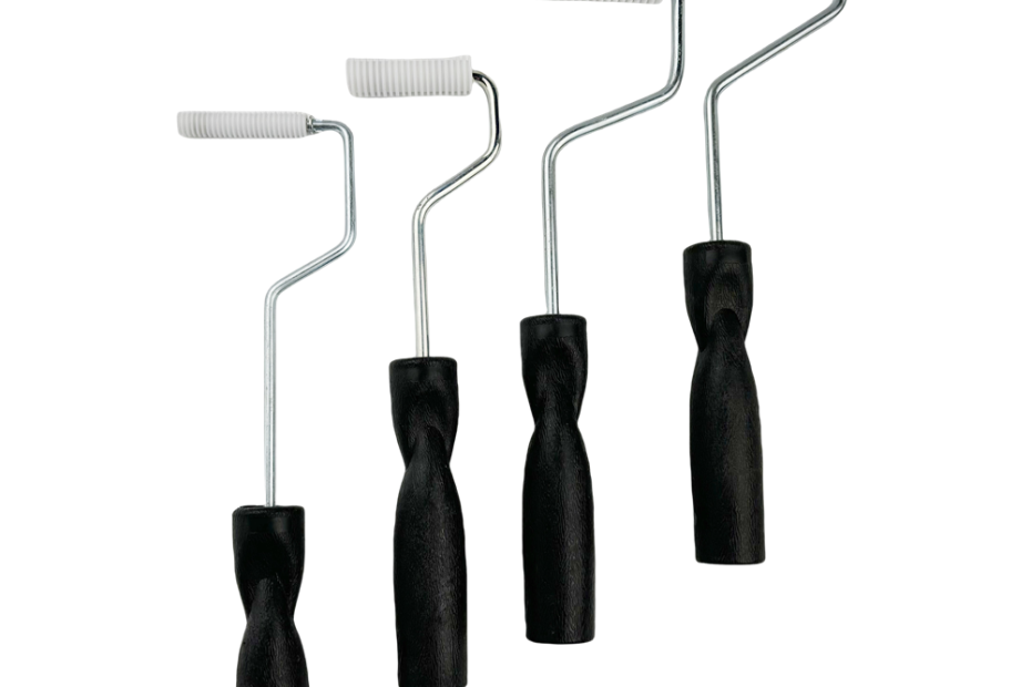
Hand lay-up is the oldest, most versatile, and still the most widely used open-mold composite fabrication process — accounting for an estimated 35–40% of all FRP/GRP production globally by tonnage. At the heart of every hand lay-up operation is the mold: the tool that defines the part geometry, surface finish, dimensional accuracy, and demolding behavior. A poorly designed or poorly constructed hand lay-up mold produces parts with dimensional variation, surface defects, premature mold wear, and excessive demolding labor — problems that compound across every production cycle. A well-engineered mold, by contrast, can produce thousands of consistent, high-quality parts over a service life of 10–20 years with only routine cleaning and waxing between cycles.
This deep dive examines FRP hand lay-up mold engineering across five dimensions: mold design principles and geometry, material selection for mold construction, surface preparation and release systems, mold maintenance and lifecycle management, and cost-performance optimization for different production volumes. The focus is on practical engineering knowledge for composite fabricators, tooling engineers, and production managers who specify, build, or purchase FRP hand lay-up molds.
Key Takeaway: The hand lay-up mold is not a passive container — it is an active engineering system where material selection, surface preparation, draft angles, and release agent chemistry collectively determine part quality, mold lifespan, and per-part labor cost. The differences between a $2,000 prototype mold and a $20,000 production mold are not cosmetic — they are dimensional, thermal, and durability-related engineering choices that directly impact the bottom line.
Mold Design Principles: Geometry, Draft & Parting Lines
Hand lay-up mold design begins with the part geometry translated into a negative cavity, but the engineering decisions that determine mold performance go far beyond simple shape inversion:
Draft Angles: The 2° Rule and Its Exceptions
The single most common mold design error — and the cause of the most demolding damage — is insufficient draft angle. For FRP hand lay-up molds, the minimum recommended draft angle is 2° on vertical surfaces parallel to the demolding direction. This applies to both male (plug) and female (cavity) mold configurations. However, several factors modify this requirement:
- Surface roughness: A mold with a polished, waxed gel coat surface (Ra < 0.1 μm) can release with 1–1.5° draft. A mold with a matte or textured surface may require 3–5° draft to compensate for mechanical interlock between the part and mold surface asperities.
- Part thickness and shrinkage: Thicker laminates (above 6 mm) generate higher exothermic temperatures during cure (up to 120–150°C for polyester resin with high catalyst levels), causing greater thermal expansion of the mold and more cure shrinkage of the part. Parts with 10+ mm thickness may require an additional 0.5–1° draft to account for shrinkage-induced gripping of the mold.
- Part depth: Draft angle requirements increase with part depth. A 100 mm deep vertical wall at 2° draft provides 3.5 mm of clearance at the top — adequate for a flexible FRP part. A 500 mm deep wall at the same 2° provides 17.5 mm clearance — more than enough. The absolute clearance, not the angle alone, determines demolding ease.
- Mold material: Composite molds (FRP/GRP) have a coefficient of thermal expansion (CTE) of 15–20 × 10⁻⁶/K, which is relatively close to the part CTE (12–18 × 10⁻⁶/K). Steel molds (CTE 12 × 10⁻⁶/K) may require slightly more draft because the mold and part expand at different rates during the exothermic cure, potentially tightening the part onto the mold at peak temperature.
Parting Line Placement
Hand lay-up molds can be single-piece (open face) or multi-piece (split mold) depending on part geometry complexity. Single-piece molds are used for parts where all surfaces are visible and accessible from one side — boat hulls, shower stalls, truck body panels, and architectural cladding. Multi-piece molds are required when the part has undercuts, reverse draft, or enclosed features that would trap the part on a single-piece mold.
Parting line placement follows three rules: (1) position the parting line along the part’s natural edge or a cosmetic feature line where the witness line (the slight resin flash at the mold joint) is least visible; (2) avoid parting lines on Class A (visible) surfaces wherever possible — move them to edges, flanges, or non-visible zones; (3) ensure that each mold section has positive draft from its respective demolding direction — a parting line on a surface with 0° draft guarantees demolding difficulty and mold damage.
Mold Construction Materials: The Five Options
The choice of mold construction material is the single most consequential decision in hand lay-up mold engineering. It determines mold cost, lead time, surface finish quality, thermal behavior, durability, and maximum production volume. The five primary options are:
| Material | Relative Cost | Tool Life (Cycles) | Surface Finish | Thermal Stability | Best Application |
|---|---|---|---|---|---|
| FRP/GRP Composite Mold | $$ | 500–5,000 | Excellent (gel coat) | Moderate | Production, marine, automotive |
| Steel (P20, 718H, H13) | $$$$$ | 50,000–500,000 | Excellent (polished) | Excellent | High-volume compression/SMC |
| Aluminum (5083, 6061-T6) | $$$ | 1,000–10,000 | Good (polished) | Good | Low-pressure, prototype |
| Machined Tooling Board | $ | 10–200 | Good (sealed + painted) | Poor (50–60°C max) | Prototype, one-off, master plug |
| Cast Polyurethane | $–$$ | 50–500 | Good | Poor (60–80°C max) | Short-run, decorative |
FRP/GRP Composite Molds: The Industry Standard
FRP composite molds are constructed using the same hand lay-up process as the parts they will produce, but with higher-performance materials and more stringent construction standards. The typical construction sequence is:
- Master plug/pattern: A dimensionally accurate master model of the part, typically machined from tooling board, MDF, or high-density polyurethane foam, finished to the exact surface quality desired on the final part. The plug is the positive; the mold is the negative taken from it.
- Tooling gel coat: A high-temperature-resistant, chemical-resistant gel coat (typically isophthalic-NPG or vinyl ester based) applied at 0.5–0.8 mm thickness to the plug surface. Tooling gel coats are formulated for higher heat distortion temperature (HDT > 120°C vs. 80–90°C for general-purpose gel coats) and lower shrinkage to maintain dimensional accuracy through multiple exothermic cure cycles.
- Skin coat: A thin layer (0.5–1.0 mm) of resin-rich laminate — typically a 30 g/m² surface veil or lightweight CSM (225–300 g/m²) — applied behind the gel coat to prevent fiber print-through and create a resin-rich barrier layer.
- Bulk laminate: Multiple layers of chopped strand mat (CSM) and/or woven roving built up to the required mold thickness — typically 6–12 mm for small-to-medium molds and 12–20 mm for large molds. The laminate schedule alternates CSM (for interlayer adhesion and resin content) with woven roving (for stiffness and strength).
- Reinforcement structure: Steel or aluminum tube framing, plywood ribs, or foam-core sandwich panels bonded to the back of the mold to provide rigidity, prevent sagging under the weight of wet laminate, and provide a stable base for the mold to sit on during lay-up.
- Post-cure: The completed mold is post-cured at a temperature 10–20°C above the intended maximum service temperature, typically 60–80°C for 8–16 hours for polyester molds, to complete the cross-linking reaction and stabilize dimensions before the first production cycle.
The primary advantage of FRP composite molds is thermal expansion compatibility with the part — both mold and part are fiberglass-reinforced polyester, so they expand and contract at essentially the same rate during the exothermic cure cycle. This eliminates the differential expansion stresses that can cause part cracking or mold damage in steel or aluminum molds.

Release Systems: Chemistry, Application & Troubleshooting
The release system is the interface between mold and part — and the source of more hand lay-up production problems than any other single factor. A release failure (sticking) destroys both the part and potentially the mold surface. The three categories of release agents are:
1. Wax-Based Release Systems (Paste Wax)
Carnauba-based or synthetic paste waxes are the traditional release system for hand lay-up. Applied in thin coats, buffed to a haze, and built up in multiple layers (typically 3–5 coats for a new mold, with a minimum 30-minute cure between coats), wax forms a sacrificial, renewable release film on the mold surface. Advantages: low cost, easy to apply, compatible with all resin systems, forgiving to application technique. Disadvantages: requires re-application every 1–3 cycles for production molds, can build up in corners and details (causing dimensional issues), temperature-sensitive (softens above 60–70°C depending on wax grade).
2. Semi-Permanent Release Systems (Polymer-Based)
Semi-permanent release agents are solvent-based or water-based polymer solutions (typically siloxane, PTFE, or cross-linking acrylic chemistry) that chemically bond to the mold surface to form a durable, multi-cycle release film. They are applied by wiping or spraying, allowed to flash off, and typically require a light buff. A properly applied semi-permanent release can last 5–20 release cycles before re-application. Advantages: fewer applications (higher productivity), no wax build-up, better chemical resistance to styrene and aggressive resin systems, consistent release performance. Disadvantages: higher cost per liter, more sensitive to application technique (film thickness and coverage must be consistent), some formulations are incompatible with specific gel coat or resin chemistries.
3. PVA (Polyvinyl Alcohol) Release Films
PVA is a water-soluble polymer applied as a liquid that dries to form a continuous, physical barrier film between the mold and the part. It is sprayed or wiped onto the mold surface, dries to a thin transparent film (15–30 minutes at 20°C), and is removed after each cycle by peeling or water washing from the part and reapplied to the mold. Advantages: absolute release guarantee (the film physically separates mold from part), compatible with all resin systems including aggressive vinyl esters and epoxies, useful for new mold break-in where the gel coat surface hasn’t fully cured. Disadvantages: re-application every cycle (high labor), film can trap surface detail (not suitable for Class A surfaces), difficult to achieve uniform thickness on complex geometries, water solubility limits use in humid environments.
Mold Maintenance & Lifecycle Management
A well-maintained FRP hand lay-up mold can produce 2,000–5,000 parts over a 10–15 year service life. Mold failure — surface cracking, gel coat delamination, dimensional distortion — is almost always the result of accumulated maintenance neglect rather than a single catastrophic event:
- Release agent management: The #1 cause of premature mold surface damage is inadequate or inconsistent release agent application. Every production facility should maintain a mold log recording: date, cycle number, release agent type and application method, number of coats applied, and any sticking or release difficulty observed. This log is the single most valuable tool for diagnosing release problems before they cause mold damage.
- Gel coat inspection: Inspect the mold gel coat surface under oblique lighting (glancing light at 15–30° from the surface) after every cleaning cycle. Look for: crazing (micro-cracks in the gel coat, typically caused by thermal shock or excessive exotherm), blisters (osmotic or trapped-solvent bubbles between gel coat and laminate), scratches (from abrasive cleaning or careless tool contact), and gel coat wear-through (exposed glass fiber, typically at sharp corners or high-abrasion zones). Catch crazing early — it can be sealed with a catalyzed gel coat repair before it propagates into the laminate.
- Cleaning protocol: Remove cured resin drips, gel coat overspray, and release agent build-up using non-abrasive cleaners formulated for FRP molds. Never use steel wool, Scotch-Brite, or abrasive scouring pads on a mold surface — these create micro-scratches that accumulate over cycles, progressively degrading the surface finish and increasing release difficulty. For stubborn contamination, use a plastic razor blade or a solvent wipe (acetone or MEK) followed immediately by re-waxing — solvents strip the release film along with the contamination.
- Thermal management: FRP molds are thermal insulators (thermal conductivity approximately 0.2–0.3 W/m·K, vs. 50 W/m·K for steel). Heat from exothermic resin cure builds up in the mold rather than dissipating. For production rates above 2–3 cycles per shift, active mold cooling (forced air across the mold back surface, or embedded cooling channels in the mold laminate) becomes necessary to keep the mold surface below the gel coat’s HDT and prevent gradual thermal degradation.
- Dimensional verification: Periodically (every 100–200 cycles, or whenever a new batch of parts shows fit-up problems), verify the mold dimensions at critical datums using a laser tracker, CMM, or precision templates. FRP molds can exhibit gradual creep or distortion over time due to residual cure shrinkage of the mold laminate, thermal cycling fatigue, or mechanical loading from heavy wet laminates. Catch dimensional drift early — small corrections to the mold support structure or localized rework of the mold surface are far cheaper than a new mold.
Cost-Performance Optimization: Matching Mold Investment to Production Volume
The most expensive mold is not the one with the highest purchase price — it’s the one that is over-specified for its production volume (capital tied up in unnecessary durability) or under-specified for its production volume (premature failure causing production downtime and rework costs). The table below provides a decision framework for matching mold investment to production requirements:
| Production Volume | Recommended Mold Material | Typical Mold Cost Range | Cost per Part (Mold Amortization) | Expected Mold Life |
|---|---|---|---|---|
| 1–10 parts (prototype) | Tooling board / Cast PU | $500–3,000 | $50–300 | Single project |
| 10–100 parts (short run) | FRP composite (light build) | $2,000–8,000 | $20–80 | 2–5 years |
| 100–1,000 parts (medium run) | FRP composite (heavy build) | $6,000–20,000 | $6–20 | 5–10 years |
| 1,000–10,000 parts (production) | FRP + aluminum/steel frame | $15,000–50,000 | $1.50–5 | 10–15 years |
| 10,000+ parts (high volume) | Steel or aluminum (machined) | $30,000–150,000+ | $0.30–1.50 | 15–25 years |
Frequently Asked Questions
How long does it take to build an FRP hand lay-up mold?
Typical lead times: Small/simple mold (< 1 m²): 3–7 days from master plug completion. Medium mold (1–3 m², moderate complexity): 2–4 weeks including master plug, mold lamination, post-cure, and surface finishing. Large/complex mold (boat hull, architectural panel > 3 m²): 4–12 weeks depending on size, complexity, and reinforcement structure requirements. The master plug (pattern) typically accounts for 40–60% of the total mold build time — it must be dimensionally perfect because every imperfection is transferred to the mold and subsequently to every part. Skimping on plug quality to save schedule is the most expensive shortcut in mold making.
What is the difference between a male and female hand lay-up mold?
A female mold (cavity) produces parts where the mold-side surface is the visible/Class A surface — the exterior of a boat hull, the face of an architectural panel, the outside of a truck body panel. The laminate is built up inside the cavity, and the outer surface quality is determined by the mold surface. A male mold (plug/positive) produces parts where the mold-side surface is the non-visible/back surface — the interior of a tank, the back of a decorative panel. The laminate is built up on the outside of the plug. Female molds are far more common because most FRP applications require a high-quality visible exterior surface, and achieving that surface quality by finishing the outer laminate (male molding) is far more labor-intensive than molding against a polished gel coat cavity (female molding).
How do I prevent gel coat surface porosity on FRP molds?
Tooling gel coat porosity — tiny pinholes in the cured gel coat surface — is caused by entrapped air or styrene vapor bubbles that were present in the gel coat layer when it cured. Prevention: (1) Allow the catalyzed gel coat to de-aerate for 5–10 minutes after mixing before application — this lets mixing-induced air bubbles rise out. (2) Apply gel coat at the manufacturer’s recommended wet film thickness (typically 0.5–0.8 mm for tooling gel coats) — too thin and bubbles can’t escape; too thick and styrene vapor trapped beneath the surface creates voids. (3) Use a grooved consolidation roller after spray application to mechanically work air out of the gel coat film. (4) Control workshop temperature and humidity — gel coat applied in high humidity (>80% RH) or low temperature (<15°C) conditions is far more prone to porosity. (5) If porosity appears in a cured mold, it can be spot-repaired by wet-sanding the affected area (400→600→800 grit), filling pinholes with catalyzed gel coat paste applied with a squeegee, covering with Mylar film (to cure without air inhibition), and wet-sanding flush.
When should I consider switching from hand lay-up to closed molding (RTM, compression)?
Consider transitioning from hand lay-up to closed molding when: (1) Production volume exceeds approximately 500–1,000 parts per year — at this volume, the higher mold investment for RTM or compression tooling is justified by reduced labor and faster cycle times. (2) Part quality consistency becomes a bottleneck — hand lay-up inherently has operator-to-operator and shift-to-shift variation in resin content, void content, and thickness; closed molding provides process-controlled repeatability. (3) Styrene emission regulations (e.g., EPA NESHAP, EU VOC Directive) make open-mold compliance increasingly difficult — closed molding captures styrene within the closed tool cavity, reducing emissions by 90–98% vs. open molding. (4) Both surfaces of the part require Class A finish — hand lay-up produces one mold-side surface (good) and one hand-worked surface (operator-dependent); closed molding produces two mold-side surfaces. However, hand lay-up retains advantages for very large parts (boat hulls > 10m, wind turbine blades), very low volume production, and parts with extreme size or geometry complexity where closed mold investment is prohibitive.
At TSTAR Mold, we design and manufacture FRP hand lay-up molds for marine, architectural, automotive, and industrial composite applications. Our mold-making services include master plug/pattern fabrication, FRP composite mold construction, and steel/aluminum tooling for compression and RTM processes. Contact our tooling engineering team to discuss your mold requirements, request a mold construction quotation, or schedule a mold design review.
Standards & References
The following industry standards are referenced in this article: