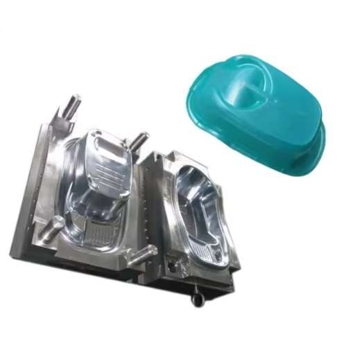
A conformally cooled injection mold cuts cycle time 25-40% versus a conventionally drilled mold for the same part geometry. Conformal channels follow the cavity contour at a uniform 1-2X diameter offset instead of straight intersecting drill holes. The economic decision: a single DMLS-printed mold insert costs $8,000-15,000 for maraging steel (MS1) versus $2,000-4,000 for conventional machining. At 50,000 parts per year, payback arrives in 8-14 months from cycle time savings alone.
Cycle Time Economics and ROI Analysis
| Parameter | Conventional Cooling | Conformal Cooling |
|---|---|---|
| Cycle time (mid-size housing) | 35-45 seconds | 22-28 seconds |
| Temperature variation across cavity | ±15-25°C | ±5-8°C |
| Mold insert cost | $2,000-4,000 | $8,000-15,000 |
| Warpage (flatness deviation) | 0.3-0.8 mm | 0.1-0.3 mm |
| Insert production method | Drilled + plugged | DMLS/SLM 3D printing |
| Channel diameter range | 6-12 mm (straight) | 3-8 mm (curved/helical) |
| Annual production for breakeven | Baseline | 80,000-120,000 parts |
Channel Design Rules That Actually Work in Production
Production-proven design rules: maintain a minimum 2X channel diameter wall thickness between the cooling channel and the cavity surface (3 mm minimum). Channel diameter should be 4-8 mm. Below 4 mm, pressure drop across the circuit exceeds 3-4 bar, requiring booster pumps. Above 8 mm, Reynolds numbers drop below turbulent transition at typical 2-4 m/s flow rates, cutting heat transfer efficiency by 30-40%. Helical channels around cylindrical cores (bosses, collars) provide the highest ROI — they are simple to design and eliminate the hot spots that cause sink marks on thick bosses. For cooling circuits longer than 2 meters total length, abrasive flow machining (AFM) to reduce surface roughness from as-printed 8-15 µm Ra down to 3-5 µm Ra keeps pressure drop within manageable limits.
DMLS Material Selection for Mold Inserts
Maraging steel MS1 (1.2709) dominates conformal cooling insert production. It prints at 40 µm layer thickness on EOS M290-class machines, achieves 50-52 HRC after age hardening at 490°C for 6 hours, and polishes to SPI A-2 finish. Thermal conductivity is 15-20 W/m·K — about 60% of P20 tool steel (30 W/m·K) — which means you need 30-40% more channel surface area for equivalent heat removal. For high-volume production exceeding 500,000 cycles, H13 tool steel printed via DMLS achieves 48-50 HRC with better thermal fatigue resistance but requires post-print HIP (hot isostatic pressing) at 1,100°C/100 MPa to eliminate internal porosity below 0.1%, which is necessary for acceptable polishability on visible surfaces.
Frequently Asked Questions
How smooth do DMLS conformal cooling channels need to be?
As-printed channel surfaces have 8-15 µm Ra roughness. This roughness actually improves turbulent heat transfer by 10-15% compared to smooth channels (increased surface area and flow disruption at the wall). However, it also increases pressure drop by 15-25%. For circuits longer than 2 meters total length, abrasive flow machining (AFM) to reduce roughness to 3-5 µm Ra is recommended to manage pressure drop.
Can conformal cooling be retrofitted to an existing mold?
Typically no — conformal cooling requires printing the insert geometry with channels inside it. The exception: for large molds exceeding 500 mm, individual insert blocks (cores, cavity sections) can be replaced with DMLS-printed conformally cooled versions while retaining the original mold base. This partial retrofit costs 40-60% of a new mold and delivers 50-70% of the cycle time reduction.
What coolant flow rate do conformal channels need?
Target a Reynolds number above 4,000 to ensure turbulent flow, which provides 3-5X higher heat transfer coefficient than laminar flow. For a 6 mm channel with water at 20°C, this requires approximately 8-10 L/min per circuit. If your mold temperature controller maxes out at 6 L/min per circuit, either split the cooling circuit into parallel branches or increase channel diameter to 8 mm.
Does conformal cooling eliminate the need for mold temperature controllers?
No — you still need a temperature control unit (TCU), but you can run it differently. With conformal cooling, many molds can run at 10-15°C higher coolant temperature because the uniform heat removal prevents local hot spots that would otherwise require overcooling. This reduces condensation risk in humid environments and cuts chiller energy consumption by 15-25%.
What is the typical lead time for a conformally cooled insert?
DMLS printing of a mid-size insert (200x150x50 mm) takes 18-36 hours on an EOS M290. Post-processing — support removal, stress relief at 480-520°C, age hardening, and finish machining of mating surfaces — adds 3-5 working days. Total lead time from CAD to production-ready insert: 7-10 working days for standard MS1, or 12-15 working days for H13 with HIP processing.
For related mold manufacturing topics, see our articles on automotive hood mold design and AC plastic component tooling. Industry standards and further reading: Society of Plastics Engineers (SPE) mold design guidelines, and VDI 3405 for additive manufacturing processes in tooling applications.