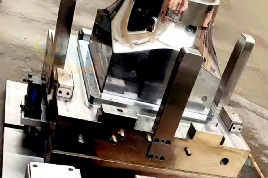
An SMC mold at a Tier-1 automotive supplier in Tennessee was making truck hood outer panels—Class A surface, painted, zero-defect spec. The parts were coming out with a recurring porosity pattern: small circular voids, 0.5-1.5mm diameter, clustered in a band about 150mm from the charge center, consistent across every shot. The tooling engineer tried increasing the clamp tonnage from 1,200 to 1,500 metric tons—no change. He tried adjusting the charge pattern from a single centered rectangle to two offset strips—the porosity moved but didn’t disappear. He tried reducing the charge coverage from 70% to 55%—the porosity got worse because there was more flow distance and more trapped air to push out. The fix, when they found it after three weeks of trial and error, was embarrassingly simple: the vent grooves on the shear edge were 0.03mm deep instead of the specified 0.05mm, and the chrome plating shop had partially filled them during the last reconditioning cycle. A $400 re-cut of the vents on a surface grinder solved a problem that had already cost $60,000 in scrap, downtime, and overtime. SMC mold venting is the least glamorous part of tool design—no one puts vent grooves in their portfolio photos—but it’s the part that separates a mold that runs first-shot-good from a mold that fights you for its entire production life, and the difference often comes down to fractions of a millimeter.
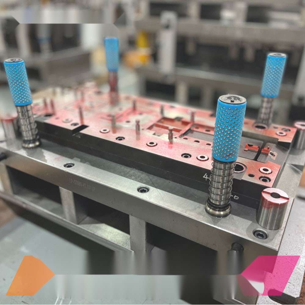
Understand SMC Mold Venting — Why Gas Gets Trapped
SMC—sheet molding compound—is a thermoset composite that cures under heat and pressure in a matched-metal mold. The material arrives at the press as a roll of tacky, leather-like sheet, typically 3-6mm thick, consisting of chopped glass fibers (25-30% by weight, 25-50mm fiber length) dispersed in a filled, pigmented, and catalyzed unsaturated polyester or vinyl ester resin paste. The paste contains about 40-50% filler by weight—calcium carbonate is the default for general-purpose SMC, alumina trihydrate for fire-retardant grades—plus styrene monomer as the reactive diluent, a peroxide initiator (usually tert-butyl peroxybenzoate or similar), an internal mold release agent (zinc stearate), and a thickening agent (magnesium oxide or magnesium hydroxide) that increases the compound viscosity from a tacky paste at layup to a leather-like solid at room temperature over a maturation period of three to five days. When the SMC charge is placed in a heated mold at 140-160°C and compressed, three things happen simultaneously: the material viscosity drops by three to four orders of magnitude as the temperature rises through the glass transition of the thickened polyester, allowing the charge to flow and fill the cavity; the peroxide initiator decomposes, generating free radicals that crosslink the polyester chains with styrene bridges, transforming the liquid resin into a rigid, three-dimensional thermoset network; and volatile compounds—styrene monomer, moisture absorbed from ambient humidity during charge preparation, entrained air from the compounding and sheet-making process—are driven out of the flowing material as gases. Those gases are the source of porosity. If they can’t escape the cavity before the material cures and locks them in place, they become voids in the finished part. The physics of SMC flow makes the venting problem harder than it looks. SMC doesn’t flow like a liquid filling a cavity from the bottom up. It flows as a plug—a viscous, fiber-filled front that moves through the cavity like a piston, pushing air ahead of it. If the charge covers 60% of the cavity area and the remaining 40% is open, the air in that open volume has to go somewhere. Ideally it exits through vents at the periphery of the cavity—at the shear edge, where the two mold halves meet. But the SMC front can also trap air by converging from two directions around a core or a rib, creating an isolated air pocket that has no path to a vent. The fiber content matters for venting because the fibers restrict the flow of gas through the material. A compound with 30% glass by weight, 25mm fibers, has a gas permeability that is roughly one-tenth that of the unfilled resin paste. What this means in practice is that gas generated in the center of the charge—where the material is thickest and the styrene vapor pressure is highest—can’t easily migrate to the edges of the charge and escape. It has to be given a path, and that path is the venting system.
The distance any gas bubble must travel to reach a vent should be shorter than the distance the SMC flow front travels before the material gels. At typical SMC molding conditions—145°C mold temperature, 60-90 second cure time, 30-50 MPa clamp pressure—the gel time of the material at the mold surface is 15-25 seconds. In that window, the SMC has to flow, fill, and vent. After gelation, gas bubbles are locked in place permanently.
Step 1: Size the Vent Grooves Correctly
Vent grooves in an SMC mold are shallow channels ground or machined into the parting line surface of one mold half, usually the cavity side, extending from the cavity edge outward toward the atmosphere. The groove cross-section is typically a rectangle or a trapezoid, and the dimensions are tiny—this is where most venting problems start. The groove depth determines how much gas can flow through the vent, but it also determines whether the SMC material will flash into the vent during molding. A groove that’s too deep vents well but fills with cured SMC, creating a flash line that requires a trimming operation and eventually clogs the vent entirely. A groove that’s too shallow doesn’t flash but also doesn’t vent enough gas, leaving porosity in the part. The practical range for SMC vent groove depth is 0.03 to 0.08mm—that’s 30 to 80 microns, about the thickness of a human hair, and it’s measured with a dial indicator on the mold surface after grinding. Vent groove width is less critical than depth for gas flow. A width of 2-4mm is standard, but the important parameter is the total vent cross-sectional area relative to the volume of air and volatiles that need to escape. A useful rule of thumb: the total vent area should be at least 0.5% of the projected cavity area. For a mold with a projected area of 0.5 square meters, that’s 2,500 mm² of total vent cross-section, which distributed around a parting line perimeter of 4 meters means an average vent depth of about 0.06mm if the total vent width (number of vents × width per vent) covers half the parting line. The vent groove length—the distance gas has to travel through the narrow channel to reach atmosphere—should be as short as practical. A 5-10mm land length is adequate for most SMC molds. Beyond 15mm, the flow resistance through the shallow channel becomes significant, and the venting efficiency drops. If the mold design requires a longer land (for strength, to avoid breaking through the edge of the tool steel), increase the groove depth slightly in the land region—a stepped vent with a 0.05mm deep × 5mm long land opening into a 0.5mm deep × 10mm wide relief groove works well and doesn’t flash because the SMC loses its ability to flow before it reaches the deep section. The vent groove spacing around the parting line perimeter matters particularly when you have ribs, bosses, or other cavity features that create flow-front convergence zones. As a starting point, space vents 50-80mm apart around the entire parting line, with closer spacing—down to 25mm—in the areas of the mold that fill last, which are typically the corners farthest from the charge location and the areas around deep ribs or cores.
Step 2: Position Vents Where the Air Actually Goes
Vent placement is more art than science if you’re doing it by trial and error, and more science than art if you have a mold-filling simulation. SMC flow simulation software—Moldflow, Moldex3D, and specialized packages like ESI PAM-COMPOSITES—can predict the SMC flow front progression, show where air pockets will form, and calculate the gas pressure in those pockets as a function of vent location. For a new mold, running a flow simulation and placing vents at the predicted last-to-fill and air-pocket locations is standard practice at any tool shop that builds production SMC tooling. For an existing mold that’s producing porosity, the diagnostic approach is a short-shot series: incrementally reduce the charge weight so that the mold doesn’t fully fill, and examine the short-shot parts to see how the flow front progressed and where it stopped. The last areas to fill are where the vents need to be. A short-shot at 95% fill, 90%, 85%, and 80% gives you a map of the flow progression that will tell you more about your venting than any simulation. Beyond the parting line, vents may also be needed at internal locations—at the tops of ribs, at the ends of blind pockets, and around ejector pins. Ejector pins themselves can serve as vents if they are ground with a slight flat or groove along one side—a practice called “venting the ejector pin.” A flat 0.03-0.05mm deep ground onto one side of a 12mm diameter ejector pin provides a vent path with a cross-sectional area of about 0.4-0.6 mm², which is meaningful for venting a local gas pocket. The pin clearance itself (typically 0.01-0.02mm diametral) is too small to vent gas effectively—it’ll vent some air over many cycles, but not fast enough to clear a gas pocket in the 15-25 second flow-and-fill window. Porous sintered metal vent inserts—typically made from sintered stainless steel with 20-40% porosity and pore sizes of 5-20 microns—can be installed in areas where parting-line vents can’t reach. These inserts allow gas to pass through the insert body while blocking the SMC material (the fibers can’t penetrate the micron-sized pores, and the resin viscosity at molding temperature is too high to flow into them before it cures). Sintered vents cost $50-200 per insert depending on size, and they require occasional cleaning—a solvent soak followed by compressed air back-flushing every 5,000-10,000 cycles—but they solve venting problems in locations that no groove vent can reach, like the bottom of a deep, narrow rib or the center of a large flat area far from the parting line.
Step 3: Use Vacuum Assist to Pull Gas Out
For SMC parts with Class A surfaces—automotive body panels, truck hoods, tractor fenders, any part that will be painted and inspected from arm’s length—vacuum-assisted venting has become standard practice in the last decade. The concept is straightforward: instead of relying on the SMC flow front to push gas out through passive vents against atmospheric pressure, you connect the vent channels to a vacuum pump that pulls a negative pressure of 50-80 kPa (0.5-0.8 bar below atmospheric) on the mold cavity during the flow and fill phase. The vacuum does three things: it increases the pressure gradient driving gas out of the cavity by a factor of about two (the driving force goes from mold-internal pressure minus atmospheric to mold-internal pressure minus vacuum pressure), it removes the back-pressure that a passive vent sees from the air column in the vent channel, and it collapses air bubbles before they can become trapped by the converging flow fronts—the reduced pressure inside an air pocket makes it smaller, and a smaller bubble is less likely to be isolated by converging SMC flow. The practical implementation requires machining vacuum channels into the mold: a network of small passages, typically 3-5mm diameter drilled holes, that connect the vent grooves to a peripheral vacuum manifold machined into the mold base. The manifold connects to the vacuum pump through a quick-disconnect fitting on the side of the mold. A vacuum seal—a silicone O-ring in a groove that surrounds the cavity outside the parting line—prevents ambient air from being pulled into the mold through the parting line gap, which would defeat the vacuum and also draw contaminants into the mold. The vacuum is typically pulled for the first 20-40 seconds of the molding cycle—from the moment the mold starts to close until the material has gelled—and then vented to atmosphere for the remainder of the cure cycle. The vacuum pump should be sized for the cavity volume: as a rough guideline, the pump should be able to evacuate five times the cavity volume per second at the target vacuum level. For a mold with a cavity volume of 5 liters, a pump rated at 25 liters per second (about 1.5 m³/min) at 60 kPa vacuum is adequate. Diaphragm pumps work well for this application because they tolerate the styrene vapors that inevitably get pulled into the vacuum line—rotary vane pumps need a cold trap in the vacuum line to condense styrene before it reaches the pump oil, which adds cost and maintenance complexity. The capital cost of adding vacuum assist to an SMC mold is typically $5,000-15,000 for the pump, plumbing, seals, and controls, plus about $2,000-5,000 for the additional machining in the mold. Against the cost of a 3-5% scrap rate from porosity on a Class A part running 100,000 cycles a year, the payback is measured in months.
Step 4: Design the Shear Edge to Control Vent Timing
The shear edge—the vertical land where the core and cavity meet around the perimeter of the mold—is the primary vent path in an SMC mold, and its geometry controls when venting happens relative to the molding cycle. A shear edge is typically 8-15mm deep (vertical engagement) with a clearance of 0.03-0.08mm per side. When the mold is fully closed, the shear edge clearance provides a narrow annular gap through which gas escapes. But the gas escapes only during the final 2-5mm of mold closing—before that point, the gap is too wide to restrict the SMC from flowing out. This means the venting window is very short: the time it takes the press to close the last few millimeters, during which the SMC is simultaneously filling the cavity and generating gas. The shear edge clearance is the single most sensitive dimension in SMC mold venting. If it’s too tight—less than 0.03mm per side on a 1,000mm-long shear edge—thermal expansion of the tool steel during heat-up from room temperature to 150°C can close the gap to zero, eliminating all venting and creating a sealed cavity. If it’s too loose—more than 0.10mm per side—the SMC flashes through the gap, the flash cures, and the mold operator spends the next cycle picking cured SMC out of the shear edge with a brass scraper. The thermal expansion of tool steel (P20, H13, or similar) is about 12 × 10⁻⁶ per °C. For a 1,000mm mold dimension, heating from 20°C to 150°C adds about 1.6mm of thermal expansion. The shear edge clearance at operating temperature is what matters, not the clearance at room temperature. A shear edge that measures 0.06mm at room temperature on one side of the cavity might be 0.04mm at 150°C on that side and 0.08mm on the opposite side if the mold heating is uneven, which is common in large molds where the cartridge heaters near the sprue run hotter than the heaters near the edges. Some tooling engineers specify a shear edge with a slight taper—0.03mm at the cavity end opening to 0.08mm at the atmospheric end over a land length of 8-12mm. This tapered vent geometry provides the gas-flow benefit of a deeper groove near the atmosphere combined with the flash-prevention benefit of a tight clearance near the cavity. The taper is ground in with a surface grinder after the shear edge is machined, and it takes a skilled toolmaker about an hour per meter of parting line to do it correctly. For molds that run in production for hundreds of thousands of cycles, the shear edge clearance gradually increases due to wear—the glass fibers in SMC are abrasive, and every cycle erodes the tool steel by a fraction of a micron. A shear edge that starts at 0.05mm clearance may be 0.08mm after 100,000 cycles and 0.12mm after 300,000 cycles, at which point the flash becomes unacceptable and the shear edge needs to be welded up and re-ground or the mold insert replaced. Monitoring the flash width on production parts—a flash of 0.5mm at the first article growing to 2mm at 200,000 cycles—is a direct indicator of shear edge wear and a predictor of when the mold needs reconditioning.
Step 5: Validate with a Short-Shot Study and Cross-Section Inspection
A new SMC mold or a mold that has been reworked for venting needs a systematic validation before it enters production. The short-shot study—covered briefly in Step 2 for diagnostic purposes—is also the primary validation tool. Run the mold with progressively increasing charge weights: start at 80% of the calculated charge weight, then 85%, 90%, 95%, and finally 100%. Photograph each short-shot part with a scale bar in the frame. The 95% short-shot should show the cavity nearly filled, with unfilled areas only at the extreme ends of the flow path. If the 95% short-shot shows unfilled areas in the middle of the cavity—between ribs, around bosses, or at locations that aren’t the farthest from the charge—those unfilled areas are gas traps, not flow-short areas, and they need additional venting. The 100% fill shot should be sectioned—cut the part with a diamond saw at the locations that showed late filling in the short-shot study, and inspect the cross-sections under a stereo microscope at 10-20× magnification. What you’re looking for: spherical voids (gas porosity—venting issue), irregular voids with glass-fiber surfaces visible inside (dry glass—the resin didn’t wet out the fibers, which is a compounding problem, not a venting problem), and flat, lens-shaped delaminations between layers of the SMC charge (interlaminar porosity—caused by air trapped between the SMC plies when the charge was built, fixable by improving the charge layup procedure or adding a vacuum de-bulking step before molding). A production-quality SMC part should have zero visible porosity on the surface and less than 1% void content by volume in any cross-section when measured by image analysis. The time spent validating—one shift of press time and some saw blades—pays back in the first week of production that runs without porosity-related scrap.
Common Pitfalls to Avoid
The mold that runs perfectly on a Tuesday afternoon in December with the shop at 22°C and 40% relative humidity may porosity-scrap half the shots on a humid August morning when the shop is at 32°C and 80% RH. SMC absorbs moisture from the air—the polyester paste is hygroscopic, and the calcium carbonate filler adsorbs water on its particle surfaces. An SMC roll that has been out of its moisture-barrier bag for two hours on a humid day can pick up 0.1-0.3% moisture by weight, which doesn’t sound like much until you calculate that 0.2% of a 5 kg charge is 10 grams of water, which turns into about 12 liters of steam at 150°C molding temperature. That steam has to be vented, and vents sized for dry SMC in winter may not handle the extra gas load from humid summer conditions. The fix is strict material handling: SMC should be removed from its moisture-barrier packaging no more than 30 minutes before it goes into the mold, and the rolls should be stored in a temperature-controlled area that stays within 5°C of the press-room temperature to avoid condensation. The other seasonal trap is mold temperature variation: an SMC mold that runs at 145°C in January with the shop at 15°C may run at 155°C in July because the oil heater setpoint hasn’t been adjusted and the cooler ambient temperature was pulling heat out of the mold exterior faster in winter. A 10°C higher mold temperature shortens the gel time by roughly 30-40%, which reduces the time available for venting by the same amount. If your venting was marginal at 145°C, it’ll definitely fail at 155°C. The third common mistake—and this one is expensive because it requires re-cutting the mold—is plating over the vents. Hard chrome plating is commonly applied to SMC mold surfaces for wear resistance and release, but the chrome plate deposits preferentially on high-current-density areas, which include the sharp edges of vent grooves. A vent that was 0.06mm deep before chrome plating may be 0.03mm deep after plating if the plater didn’t mask the vents or compensate by cutting the vents deeper before plating. The specification for the chrome plating shop should explicitly state the post-plating vent depth tolerance, and the mold should be inspected with a dial depth gauge on every vent groove after plating and before the mold is returned to the press.
| Venting Parameter | Recommended Range | If Too Small | If Too Large |
|---|---|---|---|
| Vent groove depth | 0.03-0.08 mm | Porosity, burn marks, trapped gas pockets | SMC flash into vent, trimming required, vent clogs over cycles |
| Vent groove width | 2-4 mm | Insufficient gas flow cross-section | Excessive flash width, material waste |
| Total vent area (% of cavity area) | 0.5-1.0% | Back-pressure prevents complete venting | Oversize, but rarely a problem unless flash is excessive |
| Shear edge clearance (per side) | 0.03-0.08 mm | Thermal expansion may close gap to zero | Flash through shear edge, damage to parting line |
| Vacuum assist pressure | 50-80 kPa below atmospheric | Insufficient driving force for gas removal | Can pull resin into vent lines before gel |
| Vent spacing around parting line | 25-80 mm | Dead zones between vents trap gas | Excessive machining cost, no performance penalty |