
SMC mold design is one of those disciplines where the textbook gets you 80% of the way, and the other 20% — the part that decides whether your mold runs 5,000 cycles or 50,000 — comes from experience. The difference between a mold that flashes, sticks, and wears out its shear edges in six months versus one that runs quietly for years is a collection of small decisions that no CAD package flags. Here are the field-tested tips that veteran mold designers accumulate over decades.
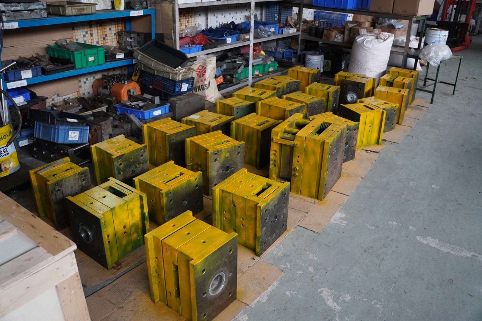
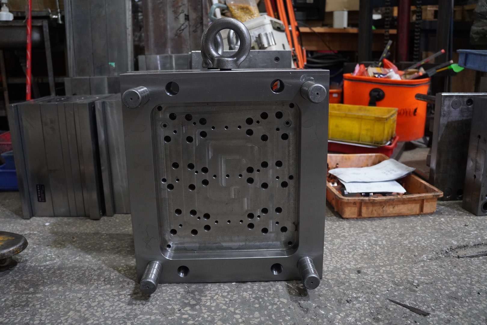

Design & Specification Tips
Start with the shear edge clearance at 0.05 mm per side, not the 0.03 mm that many design guides recommend. The tighter clearance looks better on paper but leaves no margin for thermal expansion during the first 20 cycles, when the mold is still coming up to steady-state temperature. Once the mold stabilizes at 150°C, you can tighten to 0.03–0.04 mm if flash is excessive. Second, specify the shear land length as 1.5× the maximum part wall thickness, not the standard 3–5 mm rule of thumb. A 6 mm thick SMC part needs 9 mm of shear land to maintain back-pressure during the flow phase. Parts with insufficient shear land length consistently show porosity at the flow front.
Third, never locate a shear edge directly above a heater cartridge bore. The localized thermal expansion where the steel wall is thinnest creates a hot spot that opens the shear clearance by 0.01–0.02 mm locally — exactly where you can least afford it. Offset shear edges from heater bores by at least 25 mm. Fourth, when designing for chrome plating, leave 0.025–0.050 mm of grinding stock on all cavity surfaces. Chrome builds unevenly on sharp corners (edge effect), so break all external corners with a minimum 0.5 mm radius before plating. Fifth, design the ejector system for 150% of the calculated ejection force. SMC parts shrink onto the core during cooling and the stiction can be surprisingly high — parts that eject fine in the toolroom stick in production when cycle times shorten and the part is hotter at ejection.
Heating System Design Tips
Electric cartridge heaters are the industry standard for SMC molds, but their placement makes or breaks temperature uniformity. Position heaters so the distance from heater centerline to cavity surface is uniform across the entire part — aim for 40–60 mm with no location exceeding 75 mm. Where the cavity depth changes, add supplemental heaters rather than accepting a wider spacing. A mold with 14 well-placed 800W heaters will hold ±3°C across the cavity. The same mold with 10 poorly-placed 1,200W heaters will see ±8°C variation.
Every SMC mold should have at least one thermocouple per 0.25 m² of projected area, embedded 5 mm behind the cavity surface — not in a heater bore, not on the mold exterior. Surface-mounted thermocouples read 10–20°C cooler than the actual cavity surface during production because the mold exterior is always losing heat to the ambient air. For critical dimensions, pair thermocouples on the moving and fixed halves at the same XY location. A temperature difference exceeding 5°C between the halves at any paired location indicates a heating imbalance that will warp the part.
Venting and Vacuum Tips
The most common SMC molding defect — surface porosity at the flow front — is almost always a venting problem, not a material problem. Vent grooves should be 0.05–0.08 mm deep and 6–10 mm wide, machined perpendicular to the flow direction at the last areas to fill. Space vents every 50–75 mm along the perimeter. A continuous peripheral vent (a vent groove that runs the entire part perimeter) is better than discrete vents but more expensive to machine — worth it for Class A surface parts.
If using vacuum assist, apply vacuum within the first 5 mm of mold closing stroke. Applying vacuum too late — after the shear lands have already engaged — defeats the purpose because the cavity is already sealed and the trapped air has nowhere to go except into the SMC charge. The vacuum seal (typically a silicone O-ring in a dovetail groove 15–20 mm outside the cavity) must be inspected and replaced every 5,000 cycles. A hardened or flattened O-ring leaks enough to drop vacuum from 700 mmHg to 400 mmHg — still pulling some air but not enough to eliminate porosity. Replace O-rings on a schedule, not when they fail.
Troubleshooting Common Defects
Porosity at the same location on every part almost always means insufficient charge coverage in that area — the SMC is flowing too far and trapping air. Increase charge coverage to at least 60% of the projected area (70% for complex parts) before adjusting anything else. Flash that appears only on one side of the part points to uneven mold closing — check press parallelism under load, not just at rest. A press that measures parallel with no load can deflect 0.1–0.2 mm under 1,000 tons of clamping force.
Warp that develops 24–48 hours after molding, not immediately at ejection, is post-cure shrinkage driven by incomplete cure. Increase the cure time by 15 seconds or increase the mold temperature by 5°C. A quick field test: measure the part weight immediately after molding and again 24 hours later. A weight loss exceeding 0.3% indicates residual styrene still evaporating — the part was under-cured. For parts that crack at knit lines (where two flow fronts meet), the fix is usually charge placement, not process parameters. Move the charge closer to the knit line location so the flow fronts meet earlier and at higher pressure.
Procurement & Supplier Negotiation Tips
When quoting a new SMC mold, always ask for the mold steel certification — not just the grade (P20, H13, 420SS) but the mill test report showing actual chemistry and hardness. An H13 mold that was never heat-treated after rough machining may only be 38 HRC at the cavity surface, not the 46–50 HRC you are paying for. Request hardness testing at three points on the cavity surface before accepting the mold.
Second, negotiate the tryout terms upfront. A mold that runs 20 good parts in the toolroom proves the tool works; it does not prove the tool works in your press with your SMC material. The purchase agreement should include at least one on-site tryout at your facility with your production material. Third, specify the spare parts package in the main PO, not as a separate line item. Ejector pins, heater cartridges, thermocouples, and shear edge inserts are 30–50% cheaper when bundled with the original mold than when ordered later as replacement parts.
SMC Mold Steel Selection Quick Reference
| Mold Steel | Hardness (HRC) | Best Application | Expected Cycles | Relative Cost | Caveat |
|---|---|---|---|---|---|
| P20 | 28–32 | Prototype, <5K/yr | 5K–20K | 1.0× | Wear accelerates above 20K cycles |
| H13 (heat treated) | 46–50 | Production, 10K–100K/yr | 50K–150K | 1.8× | Verify heat treat with hardness test |
| H13 + Chrome Plate | 65–70 (surface) | High volume, Class A surface | 150K–300K | 2.3× | Chrome thickness: 25–50 μm optimal |
| 420SS | 48–52 | Corrosive SMC formulations | 30K–80K | 2.5× | Lower thermal conductivity than H13 |
| P20 + Ni coating | 55–60 (surface) | Budget corrosion protection | 20K–50K | 1.4× | Nickel wears faster than chrome |
TSTAR Mold designs and manufactures SMC/BMC compression molds from single-cavity prototype tools to multi-cavity production molds running 100,000+ cycles per year. In-house CNC machining, EDM, chrome plating, and tryout press. Full engineering support from part design review through production launch and lifecycle support.