In 2023, a Tier-1 automotive composites supplier in Guangdong faced a critical mold performance gap: their existing SMC compression molds, designed for 5-8 MPa molding pressure and 140-150°C operating temperature, could not produce the Class A surface finish required for visible carbon fiber interior trim parts using epoxy prepreg. Surface pitting, incomplete cure at thin sections, and 3-5% warpage rates were driving scrap costs to 12% of production value on a contract worth $2.4 million annually. The root cause was not the prepreg material or the press — it was the mold design, which had not been adapted for prepreg’s fundamentally different processing requirements.
This case study examines how a redesigned prepreg compression mold — incorporating P20 tool steel, conformal heating channels, and precision shear edges — eliminated these defects and reduced scrap from 12% to under 2% in production volumes exceeding 15,000 parts per year.
Project Background & Context
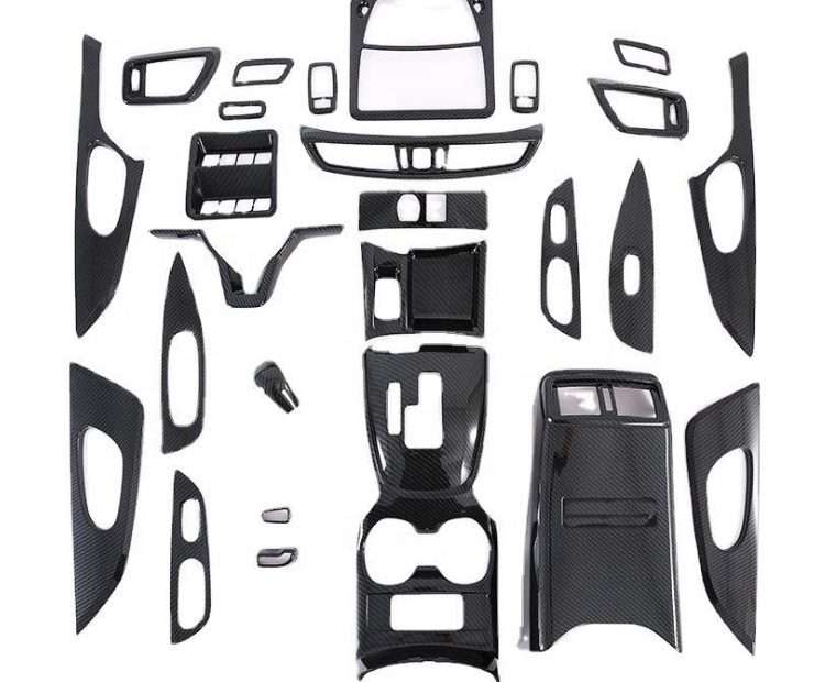
The supplier — a mid-size Guangdong composite manufacturer with 12 compression molding presses (500-2,000 ton) and 15 years of SMC molding experience — had won a contract to produce visible carbon fiber interior door trim inserts for a European luxury EV sedan. The part: a 450×120mm contoured panel with 1.2mm nominal wall thickness, 3K twill carbon fiber/epoxy prepreg, Class A gloss finish on the visible surface, and ±0.1mm dimensional tolerance across the entire perimeter to fit within an aluminum door trim bezel.
Annual volume requirement: 15,000 left-hand and 15,000 right-hand parts. Press allocation: one 800-ton compression press dedicated to this part family, operating two shifts (16 hours/day, 250 production days/year). Required cycle time: under 8 minutes per part to meet annual volume with a single-cavity mold.
Initial production used an existing SMC mold design — P20 steel cavity and core, cartridge heater layout with 5 zones, peripheral pinch-off at the part edge, and manual spray release agent application every 5-8 cycles. Within the first month of production, three defect categories emerged that could not be resolved through process parameter adjustment alone.
The Challenge: What Was at Stake
Three mold-related defect patterns were driving the 12% scrap rate:
1. Surface pitting on the Class A face: Prepreg epoxy resin releases volatile compounds (primarily residual solvent from the prepreg impregnation process and low-molecular-weight epoxy species) during the initial 30-60 seconds of heating. In the existing SMC mold, the flat peripheral pinch-off sealed the cavity before these volatiles could escape, trapping gas bubbles against the cavity surface that created surface pits 0.2-0.5mm in diameter and 0.05-0.15mm deep — visible and unacceptable on a gloss-finished cosmetic carbon fiber part.
2. Under-cure at thin edge sections: The part’s edge flange tapered from 1.2mm to 0.6mm thickness. Standard cartridge heaters placed 25mm from the cavity surface in a rectangular grid pattern delivered uniform heating to the 1.2mm sections but under-heated the thin edge by 8-12°C relative to the thicker center. The result: edge sections with glass transition temperature (Tg) of 95-105°C versus 125-135°C in the center, causing differential thermal expansion during demolding and 3-5% warpage reject rate.
3. Resin flash and fiber pull-out at the parting line: Prepreg epoxy has significantly lower viscosity at molding temperature (50-200 mPa·s at 130°C) compared to SMC molding compound (which is a high-viscosity paste). The existing mold’s 0.05mm peripheral clearance — standard for SMC — allowed resin to flash 5-10mm beyond the trim line. Worse, carbon fiber strands trapped in the flash zone were pulled from the part edge when the flash was trimmed, creating visible fiber disruption along the perimeter.
Solution Design: Why a Prepreg-Specific Mold Was Required
The engineering team designed a new mold specifically for epoxy prepreg processing, incorporating three key innovations:
Shear edge geometry with controlled venting: Instead of a flat pinch-off, the redesigned mold incorporated a stepped shear edge: a vertical land 3mm tall with 0.02-0.03mm clearance (Class B fit) between the cavity and core at the parting line, transitioning to a 0.5mm × 0.1mm deep vent channel every 50mm along the perimeter. The shear edge clearance of 0.02-0.03mm is tight enough to prevent carbon fiber (individual filament diameter 7μm, tow bundle 0.2-0.5mm) from entering the gap, while the intermittent vent channels allow volatile escape during the first 30 seconds of mold closure. This single change eliminated surface pitting — volatile gases escape through the vents, not through the laminate.
Material selection for the shear edge was critical: D2 tool steel inserts (HRC 58-60) at the shear edge, replaceable every 50,000 cycles, were used because carbon fiber is highly abrasive and would wear a P20 steel shear edge beyond the 0.03mm tolerance within 5,000-8,000 cycles.
Conformal heating/cooling channels: Cartridge heaters were replaced with oil-heated conformal channels machined into the mold following the cavity surface profile at a uniform 8mm standoff distance. This reduced temperature variation across the cavity from ±10°C to ±2°C. The conformal channels were produced by direct metal laser sintering (DMLS) of the core insert in maraging steel (MS1), allowing curved channel paths impossible to achieve by gun-drilling. The heating medium: synthetic thermal oil at 145°C ±1°C, circulated at 40 L/min through a PID-controlled temperature unit. Post-cure cooling was accomplished by switching the same channels from heating oil to cooling water (25°C) through a three-way valve, reducing demolding temperature from 130°C to 60°C in 90 seconds and eliminating warpage.
Vacuum-assisted mold closure: A silicone O-ring seal (Viton, 70 Shore A) in a dovetail groove 15mm outside the cavity perimeter enabled vacuum (50 mbar absolute) to be drawn during the first 20 seconds of mold closure. Vacuum evacuates residual air and volatiles before the mold fully closes, further reducing void formation. The vacuum system added $8,000 to mold cost (vacuum pump, plumbing, O-ring groove machining) but reduced void-related defects to essentially zero.


Implementation: Timeline, Process & Hurdles
Timeline: Mold design (3 weeks, using Siemens NX with Moldflow simulation of prepreg flow and heat transfer), steel procurement and rough machining (4 weeks), DMLS conformal core insert fabrication (2 weeks), finish machining and fitting (3 weeks), mold tryout and process validation (2 weeks). Total: 14 weeks from design kickoff to production-ready mold.
Process validation: The tryout phase ran 200 cycles across 3 days on the production press. Key process window established: mold temperature 140-145°C (measured at the cavity surface by embedded thermocouples), molding pressure 6 bar (applied after 30 seconds of low-pressure breathing at 1 bar to allow volatile venting), cure time 5 minutes (determined by DMA Tg testing — 5 minutes at 143°C achieved Tg of 132°C, exceeding the 125°C specification). Vacuum dwell: 20 seconds at 50 mbar. Cooling cycle: 90 seconds from 143°C to 60°C.
Hurdles: The DMLS conformal core insert developed a micro-crack at a channel-to-surface thin spot (2.1mm wall thickness) during the third day of tryout, causing oil weepage. Root cause: inadequate fatigue life at the thin section under cyclic thermal stress (ΔT = 85°C per cycle, 140°C → 55°C → 140°C). Solution: increased minimum wall thickness to 3.5mm at the thinnest channel section, reducing local thermal stress by 40%. The insert was re-fabricated at a cost of $4,200 and 10 additional days. This is now a standing design rule for conformal-cooled prepreg molds: minimum 3.0mm wall thickness between any coolant channel and the cavity surface.
Results: Quantitative & Qualitative Outcomes
| Metric | Old SMC-Style Mold | Redesigned Prepreg Mold | Improvement |
|---|---|---|---|
| Scrap rate | 12% | 1.8% | 85% reduction |
| Surface pitting (defects/part) | 3-8 visible pits | 0 | 100% elimination |
| Warpage reject rate | 3-5% | <0.5% | 90% reduction |
| Cycle time | 10-12 min | 7.5 min | 25-37% reduction |
| Flash trim time (seconds/part) | 45-60 | 15-20 | 65% reduction |
| Mold release application | Every 5-8 cycles (manual spray) | Every 15-20 cycles (semi-permanent coating) | 2-3× longer interval |
| Mold maintenance interval | 5,000 cycles (shear edge wear) | 50,000 cycles (D2 insert replacement) | 10× longer |
| Annual scrap cost | $288,000 (@ 12% of $2.4M) | $43,200 (@ 1.8%) | $244,800 saved/year |
Total mold investment: $78,000 (engineering design, materials, DMLS inserts, machining, tryout). Payback period: 3.8 months from scrap reduction alone, not including cycle time savings. First full year of production achieved 98.2% first-pass yield across 32,400 parts (30,000 production + 2,400 samples/testing).
Qualitatively, the conformal heating eliminated the differential cure that caused cosmetic variations — the visible carbon fiber surface now shows consistent resin clarity and gloss across the entire part, meeting the automaker’s appearance specification (distinctness of image (DOI) >85 on the BYK Wavescan, compared to DOI 65-75 with the old mold).
Lessons Learned & Replication Potential
1. SMC mold designs do not directly transfer to prepreg. The three critical differences — lower resin viscosity, volatile release during cure, and abrasive carbon fiber at the parting line — each require specific mold design features absent from standard SMC tooling. Attempting to run prepreg in an SMC mold saves the mold cost but guarantees higher scrap, longer cycles, and inconsistent quality.
2. Conformal heating/cooling is not optional for thin-wall prepreg parts. The 0.6-1.2mm thickness range common for cosmetic carbon fiber automotive parts has minimal thermal mass, making it acutely sensitive to mold temperature variation. Standard cartridge heaters at 25mm standoff cannot deliver the ±2°C uniformity required. Conformal channels at 8mm standoff with oil heating (not electric — oil provides more uniform heat transfer and faster cooling via media switching) are the minimum viable approach. The DMLS insert cost ($4,000-8,000 per insert set) is recouped within the first year through scrap reduction.
3. Shear edge design is the single most impactful mold feature. The combination of tight clearance (0.02-0.03mm), D2 steel wear inserts, and controlled vent channels solved all three original defect categories. For any prepreg compression mold, specifying the shear edge geometry — clearance, land height, vent pattern, insert material — should be the first design decision, not an afterthought. The shear edge effectively defines the boundary between a good part and scrap.
4. Vacuum assistance is cost-effective insurance. The $8,000 vacuum system cost represents 10% of the total mold investment but eliminated void-related defects entirely. For Class A visible carbon fiber parts, where a single surface void makes the part scrap, vacuum-assisted molding should be the default specification, not an option.
“We had been making SMC molds for 15 years and thought prepreg was just a material change. Within the first week of production, we realized the mold itself had to be fundamentally different. The shear edge alone paid for the entire new mold in under four months.” — Production Engineering Manager, Guangdong facility
What is the most common mistake in prepreg compression mold design?
Using SMC-style flat pinch-off parting lines instead of shear edges with controlled vent channels. Flat pinch-offs seal the cavity before volatiles can escape, causing surface pitting. A properly designed shear edge with 0.02-0.03mm clearance and intermittent vent channels allows gas venting while preventing carbon fiber pull-out at the parting line.
What mold steel is recommended for prepreg compression molding?
P20 tool steel for the main cavity and core bodies provides adequate hardness (HRC 28-32) and machinability. D2 steel inserts (HRC 58-60) at the shear edges resist abrasive wear from carbon fiber. For conformal-cooled inserts, maraging steel (MS1) processed by DMLS enables complex internal channel geometries impossible with conventional machining.
How much does a production-ready prepreg compression mold cost?
A single-cavity prepreg compression mold for a typical automotive interior part (400-600mm maximum dimension) costs $60,000-120,000 including engineering design, materials, conformal heating/cooling, shear edge inserts, vacuum system, tryout, and process validation. Mold lead time is typically 12-16 weeks from design kickoff to production-ready status.