1. Introduction
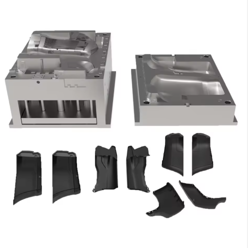
The bumper guard mold is a critical component in automotive manufacturing, requiring precise material selection and engineering to ensure impact resistance, dimensional stability, and production efficiency. Bumper guard molds must accommodate large, complex geometries while withstanding high-volume production cycles and meeting stringent safety standards. This guide outlines material selection criteria, design considerations, and manufacturing processes specific to bumper guard mold applications, focusing on ISO 10296 compliance and lightweight design requirements.
2. Material Selection for Bumper Guard Molds
2.1 Pre-hardened Steel 718H
718H is widely recognized as the workhorse material for medium-volume bumper guard molds, offering an optimal balance of machinability and durability. This nickel-enriched alloy (1.0-1.5% Ni) delivers a hardness range of 33-38 HRC and excellent polishability, making it suitable for producing bumper guard molds with Class A surface finishes. The bumper guard mold fabricated from 718H exhibits exceptional dimensional stability (±0.02mm/m) and can withstand 500,000+ cycles, ideal for mainstream automotive production. Its thermal conductivity (45 W/(m·K)) enables efficient cooling, reducing cycle times by 15-20% compared to conventional P20 steel in bumper guard mold applications.
2.2 Hot Work Tool Steel H13
For high-impact bumper guard molds requiring enhanced thermal fatigue resistance, H13 (4Cr5MoSiV1) provides superior performance in demanding production environments. This chromium-molybdenum-vanadium alloy achieves 48-52 HRC after heat treatment and demonstrates excellent resistance to thermal cycling, making it indispensable for bumper guard mold components exposed to repeated heating and cooling cycles. The material’s high toughness (15-20 J/cm² impact energy) ensures resistance to cracking during high-pressure injection, while its wear resistance supports production volumes exceeding 800,000 units. H13’s ability to maintain hardness at elevated temperatures (up to 600°C) makes it particularly suitable for processing glass-fiber reinforced plastics (GFRP) commonly used in lightweight bumper systems.
2.3 Corrosion-Resistant Stainless Steel S136
In applications requiring superior corrosion resistance and surface finish, S136 stainless steel offers exceptional performance for bumper guard molds. With 13-14% chromium content, this martensitic stainless steel forms a passive oxide layer providing 500-hour salt spray resistance per ASTM B117 testing. The bumper guard mold manufactured from S136 achieves mirror polishability (Ra ≤0.012μm) critical for visible automotive components, while its 48-52 HRC hardness ensures extended tool life. Although 40% more costly than conventional steels, S136 significantly reduces maintenance costs for bumper guard molds producing parts with corrosive additives or requiring frequent cleaning.
3. Design Considerations for Bumper Guard Molds
3.1 Structural Integrity and Impact Absorption
Bumper guard mold design must prioritize energy absorption and structural reinforcement:
- Rib reinforcement pattern: 3-5mm thick radial ribs spaced 30-40mm apart to distribute impact forces
- Hollow section design: Integral cavities reducing weight by 25% while maintaining flexural strength ≥200 MPa
- Crash box integration: Molded-in energy-absorbing structures with 1.5mm wall thickness tapering to 0.8mm
- Mounting point reinforcement: Boss structures with 8mm minimum diameter and 2° draft angle
Finite element analysis (FEA) is recommended to validate bumper guard mold performance under impact loads, ensuring compliance with FMVSS 581 and ECE R42 safety standards. The bumper guard mold should incorporate draft angles of 1.5-2° per side to facilitate demolding while maintaining structural integrity.
3.2 Cooling System Optimization
Efficient thermal management in bumper guard molds is critical for reducing cycle time and ensuring dimensional consistency:
- Conformal cooling channels: 8-10mm diameter channels following the part contour at 30mm spacing
- Beryllium copper inserts: Embedded in thick-walled sections to reduce cooling time by 30%
- Temperature uniformity: ±2°C variation across the mold surface to prevent differential shrinkage
- Flow rate optimization: 2-3 m/s to achieve turbulent flow and maximum heat transfer
For a standard bumper guard mold (1800×500×120mm), optimized cooling systems reduce cycle time from 60 to 45 seconds, significantly improving production efficiency. Moldflow simulation should be employed to validate cooling efficiency and prevent warpage in thin-walled sections.
3.3 Lightweight Design Integration
Modern bumper guard mold design must balance strength with weight reduction:
- Material substitution: LFT-G PP LGF40 composite (54 kJ/m² impact strength) reducing weight by 40% vs. steel
- Topology optimization: Computer-aided design minimizing material in non-critical areas
- Microcellular foaming: Nitrogen-assisted molding reducing density by 15-20%
- Thickness optimization: Variable wall sections (2.5-4.0mm) based on stress analysis
These lightweighting features, when incorporated into the bumper guard mold design, help automakers meet CAFE standards and improve vehicle fuel efficiency by 5-8% through reduced unsprung weight.
4. Manufacturing Processes for Bumper Guard Molds
4.1 Precision Machining Requirements
The production of bumper guard molds demands advanced machining techniques:
- 5-axis CNC milling: For complex geometries with positional accuracy of ±0.005mm
- Wire EDM: For intricate undercut features with ±0.002mm tolerance
- Surface grinding: Flatness within 0.005mm/m for critical mounting surfaces
- Laser texturing: For functional surface patterns with Ra 1.6-3.2μm roughness
Bumper guard mold components larger than 1500mm require segmented machining with subsequent assembly, ensuring each segment maintains positional accuracy within 0.01mm. Critical surfaces must be finished to Ra ≤0.8μm to prevent stress concentration points and ensure proper paint adhesion.
4.2 Surface Treatment Technologies
Bumper guard mold surfaces require specialized treatment to ensure optimal performance:
- PVD coating: Titanium nitride (TiN) or chromium nitride (CrN) coatings (3-5μm thickness) for enhanced wear resistance
- Nitriding: 0.1-0.3mm case depth with surface hardness 800-1000 HV
- Electroless nickel plating: 20-25μm thickness for corrosion protection in cooling channels
- Semi-matte finishing: Achieving PV 3952 scratch resistance standard (≥3H pencil hardness)
The surface treatment process for the bumper guard mold must undergo rigorous testing, including adhesion strength (≥50 N/cm) and abrasion resistance (≤5mg weight loss per 1000 cycles).
4.3 Assembly and Validation
Precise assembly is critical for bumper guard mold performance:
- Guide pillar parallelism: ≤0.01mm over full stroke
- Clamping force distribution: Uniform within 5% across mold surface
- Hydraulic circuit integrity: 1.5× working pressure test for 30 minutes
- Trial molding: 50-piece production run with dimensional inspection per ISO 286 standards
Large bumper guard molds should incorporate adjustable tie-bar supports to compensate for thermal expansion. The assembly process must include laser alignment verification at each stage to ensure the final bumper guard mold meets all dimensional requirements for automotive assembly.
5. Quality Control and Industry Standards
5.1 ISO 10296 Compliance
Bumper guard molds must comply with ISO 10296 standards for automotive plastic components, including:
- Impact resistance: ≥54 kJ/m² Charpy impact strength at -40°C
- Dimensional stability: ±0.5mm/m under thermal cycling (-40°C to 80°C)
- Environmental resistance: 500-hour salt spray test per ASTM B117 (no visible corrosion)
- Surface quality: Class A finish with no flow lines, weld marks, or sink marks
These requirements necessitate strict process control during bumper guard mold manufacturing, including material certification and in-process inspection at each production stage.
5.2 Performance Testing Protocol
Comprehensive testing ensures bumper guard molds reliability:
- Cycle life validation: 100,000-shot endurance test with dimensional monitoring
- Thermal fatigue testing: 10,000 thermal cycles (60-80°C) with surface integrity checks
- Impact simulation: Drop weight test (500g from 1m height) on molded parts
- Weathering resistance: 1000-hour QUV exposure with ΔE color change <2.0
Statistical process control (SPC) should be implemented for all critical bumper guard mold parameters, with control limits set at ±3σ of process capability.
6. Maintenance and Longevity Strategies
6.1 Preventive Maintenance Program
A structured preventive maintenance regimen extends bumper guard molds service life:
- Daily: Clean cavity surfaces and check for resin buildup
- Weekly: Inspect cooling channels for calcium deposits and flush with descaling solution
- Monthly: Verify alignment of guide pillars and check for signs of wear
- Quarterly: Re-polish cavity surfaces to maintain Ra ≤0.8μm finish
Maintenance records for the bumper guard mold should document all service activities, including cleaning agents used and dimensional measurements, to optimize maintenance intervals.
6.2 Repair and Refurbishment Techniques
When bumper guard mold components require repair, specialized techniques ensure minimal impact:
- Laser welding: For localized repair of damaged cavity surfaces with heat-affected zone <0.1mm
- Chrome plating: 5-10μm thickness for rebuilding worn sealing surfaces
- EDM sinking: For restoring intricate undercut geometries
- Polishing rejuvenation: Progressive diamond paste sequence to restore original surface finish
Post-repair validation requires 10-piece test molding and comparison to original CAD data to ensure the repaired bumper guard mold meets all performance specifications.
7. Advanced Technologies in Bumper Guard Mold Manufacturing
7.1 Additive Manufacturing
3D printing technologies are transforming bumper guard mold production:
- Conformal cooling inserts: Direct metal laser sintering (DMLS) producing complex cooling channels
- Topology-optimized cores: Weight reduction of 30-40% while maintaining structural integrity
- Bimetallic construction: Combining copper alloys for heat transfer with tool steel for wear resistance
These technologies reduce bumper guard mold lead times by 25-40% and improve part quality through more uniform cooling.
7.2 Digital Twin Technology
Industry 4.0 innovations are enhancing bumper guard mold development:
- Virtual tryout: Using Moldflow and similar software to simulate filling and cooling
- Real-time monitoring: Sensors embedded in the bumper guard mold to track temperature and pressure
- Predictive maintenance: AI algorithms analyzing production data to forecast maintenance needs
Digital twin technology for the bumper guard mold reduces development time by 30% and improves production yield by identifying potential issues before they cause defects.
7.3 Lightweight Material Integration
Advanced materials are enabling new possibilities in bumper guard mold design:
- Long fiber-reinforced thermoplastics (LFT) : 40% glass fiber content providing strength-to-weight ratio exceeding steel
- Carbon fiber composites: Specific modulus 3-5 times higher than aluminum
- Microcellular foaming: Density reduction of 15-20% without sacrificing structural performance
These materials, when paired with optimized bumper guard mold design, contribute to vehicle lightweighting and improved energy efficiency.
8. Conclusion
The design and manufacture of bumper guard molds require a specialized approach that balances impact performance, production efficiency, and lightweight design. By selecting appropriate materials (718H for general applications, H13 for high-impact scenarios, S136 for corrosion resistance) and implementing robust quality control measures, producers can create bumper guard molds capable of meeting the stringent requirements of modern automotive manufacturing.
The bumper guard mold industry continues to evolve through the integration of additive manufacturing, digital twin technology, and advanced composite materials. These innovations enable the production of more complex, durable, and lightweight bumper systems while supporting sustainability through reduced material usage and energy consumption.
By following the guidelines presented in this essential guide, engineers and manufacturers can develop bumper guard mold solutions that deliver consistent quality, maximize production efficiency, and support the ongoing evolution of automotive safety and performance standards. The future of bumper guard mold technology will undoubtedly bring further advancements in materials, processes, and digitalization, ensuring the industry remains at the forefront of automotive manufacturing innovation.
>>You may also like
Standards & References
The following industry standards are referenced in this article: