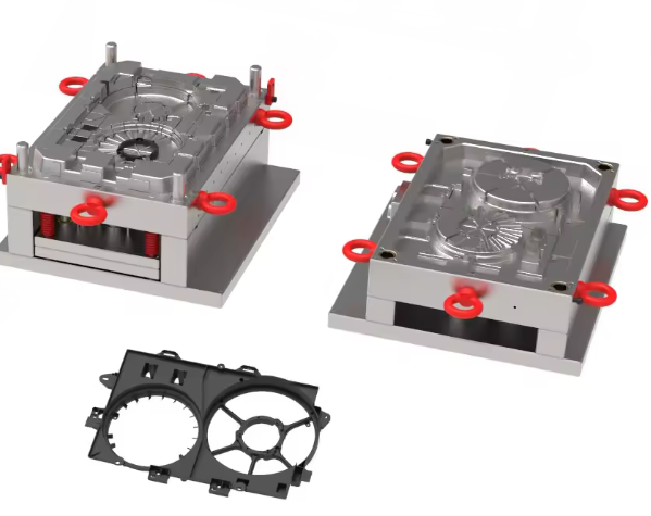
Cooling component molds play a critical role in manufacturing heat exchange parts with complex geometries and strict performance requirements. The cooling component mold must simultaneously ensure dimensional precision, thermal conductivity, and corrosion resistance to produce parts that meet automotive, HVAC, and industrial cooling system standards. This guide provides comprehensive technical specifications for mold steel selection, design considerations, and manufacturing processes specific to cooling component molds.
Material Selection for Cooling Component Molds
Hot Work Tool Steel H13
The cooling component mold relies heavily on H13 steel for its core and cavity due to its exceptional thermal fatigue resistance. With a hardness range of 48-52 HRC after heat treatment, H13 maintains structural integrity during repeated heating and cooling cycles typical in cooling component mold applications. Its composition (0.32-0.45% C, 4.75-5.50% Cr) forms stable carbides that resist wear even when processing glass-filled plastics, making it ideal for cooling component mold inserts subjected to abrasive flow.
Advanced Hot Work Steel W320
For cooling component molds operating at sustained high temperatures (exceeding 500°C), W320 steel offers superior performance with its 2.7-3.0% Mo content that enhances高温强度. This alloy maintains 40 HRC at 500°C and exhibits 49 J/cm² impact toughness, reducing the risk of thermal cracking in cooling component mold cores. The Austrian-origin steel’s uniform carbide distribution (ASTM 8 grade grain size) ensures consistent wear resistance across complex cooling component mold geometries.
High-Conductivity Copper Alloy MOLDMAX MM30
Efficient heat dissipation in cooling component molds requires specialized materials like MOLDMAX MM30, a copper-chromium-zirconium alloy with thermal conductivity 8 times higher than traditional tool steel. When used for cooling channels in cooling component molds, this alloy reduces cycle time by 30% and minimizes warpage in thin-walled cooling parts. Its HV180 hardness provides sufficient wear resistance for moderate-volume cooling component mold production.
Corrosion-Resistant Stainless Steel 2316
Cooling component molds frequently encounter cooling fluids and chemical cleaning agents, making 2316 stainless steel essential for slide assemblies and wear plates. This material offers 500-hour salt spray resistance (per ISO 9227) and maintains Ra≤0.2μm polished finish, preventing coolant contamination in cooling component mold systems. Its 48-50 HRC hardness balances wear resistance with machinability for complex cooling component mold features.
Design Considerations for Cooling Component Molds
Thermal Management System Design
The cooling component mold’s thermal efficiency depends on optimized cooling channel design. Spiral-type conformal cooling channels should follow these parameters: diameter 3-6mm, pitch 1-2× diameter, and distance to mold surface 3-8mm. CFD analysis confirms that this configuration reduces temperature variation across the cooling component mold by 40%, ensuring uniform part cooling. Properly designed cooling component mold cooling systems can reduce cycle time by 25% compared to conventional straight channels.
Dimensional Precision Requirements
Cooling component mold critical dimensions demand IT8 grade tolerances (±0.05mm) to ensure proper fit with mating parts. Flatness must be maintained within 0.1mm/m across sealing surfaces to prevent leakage. The cooling component mold’s parting line mismatch should not exceed 0.03mm, requiring precise alignment of guide pillars and bushings with 0.02-0.04mm clearance. These precision requirements ensure that the cooling component mold produces parts meeting automotive cooling system assembly standards.
Pressure Integrity Features
The cooling component mold must withstand internal pressures up to 15MPa during operation. Design features include rounded channel corners (minimum R0.5mm), reinforced gussets at pressure points, and uniform wall thickness (minimum 2mm for pressure-containing areas). Pressure testing per ISO 10297 standards verifies the cooling component mold’s integrity, requiring 1.5× working pressure for 1 hour with no measurable pressure decay.
Ejection System Optimization
Cooling component mold ejection systems must accommodate thin walls and complex geometries without causing deformation. Balanced ejector pin placement (1 pin per 100cm² projected area) with 3mm minimum diameter ensures uniform force distribution. The cooling component mold’s ejector return system should include positive stops and wear plates to maintain alignment after repeated cycling. These features prevent part distortion and extend cooling component mold service life.
Manufacturing Processes for Cooling Component Molds
Precision Machining Techniques
Producing the cooling component mold requires advanced machining capabilities. High-speed milling with carbide tools achieves 5μm positional accuracy for critical cooling channels. EDM wire cutting maintains ±0.01mm tolerance for complex cooling component mold features, while sinker EDM creates precise cooling holes with 0.05mm diameter control. These processes ensure the cooling component mold meets stringent dimensional requirements for heat exchange efficiency.
Surface Treatment Specifications
The cooling component mold’s surface finish directly impacts part quality and release properties. Cavity surfaces require SPI #3 finish (Ra 0.4μm) for general cooling parts, while visible surfaces need SPI #2 finish (Ra 0.2μm). Specialized treatments include:
- Nitriding (0.1-0.2mm case depth) for core inserts to improve wear resistance
- TiAlN coating (2μm thickness) on hot runner components of the cooling component mold
- Electropolishing of cooling channels to reduce flow resistance by 15%
Additive Manufacturing Applications
Laser powder bed fusion (LPBF) enables complex cooling component mold features unachievable with conventional methods. Conformal cooling Inlay produced via LPBF show 20% better heat transfer compared to drilled channels. The cooling component mold’s 3D-printed inserts can be integrated into traditional steel frames, combining the benefits of additive and subtractive manufacturing. This hybrid approach reduces cooling component mold lead time by 35% for complex geometries.
Assembly and Validation Procedures
Cooling component mold assembly requires meticulous attention to detail. Critical steps include:
- Guided pillar and bushing installation with 0.01mm runout tolerance
- Cooling circuit leak testing at 10bar pressure for 30 minutes
- Hot runner system calibration to ensure uniform melt distribution
- Trial molding with process parameter recording for future cooling component mold setup
These procedures ensure the cooling component mold performs consistently throughout its production life.
Process Parameters for Cooling Component Molds
Polypropylene (PP) Processing
For PP cooling components, the cooling component mold requires specific parameters:
- Barrel temperature profile: 200-230°C (zone 3-4)
- Mold temperature: 40-60°C (regulated via proportional control valves)
- Injection pressure: 80-100MPa (with 3-stage pressure profile)
- Injection speed: 60-90mm/s (faster for thin-walled sections)
- Cooling time: 15-20 seconds (optimized via CAE simulation)
These settings balance production efficiency with part quality in the cooling component mold.
Glass-Filled Nylon Processing
When molding 30% glass-filled PA66 in the cooling component mold:
- Melt temperature: 260-280°C
- Mold temperature: 80-100°C
- Injection pressure: 100-120MPa
- Hold pressure: 70% of injection pressure
- Screw recovery speed: 80rpm (to minimize fiber breakage)
The cooling component mold must include hardened inserts (52-54 HRC) to withstand abrasive wear from glass fibers.
Process Monitoring and Control
Advanced cooling component mold systems incorporate real-time monitoring:
- In-cavity pressure sensors (±0.5% accuracy)
- Mold temperature sensors (±1°C resolution)
- Part weight monitoring (±0.1g precision)
- Cooling flow rate meters (±2% of reading)
This data acquisition enables SPC control of the cooling component mold process, reducing variation by 40% compared to manual setup.
Quality Control and Validation
Dimensional Inspection Protocol
The cooling component mold undergoes comprehensive metrology:
- CMM inspection of all critical dimensions (5μm uncertainty)
- Optical comparator analysis of complex profiles
- Surface finish verification with contact profilometer
- 3D scanning for form and contour analysis (±0.02mm accuracy)
These inspections ensure the cooling component mold meets design specifications before production.
Material Verification Testing
Cooling component mold materials require certification including:
- Chemical composition analysis (spectrometry)
- Hardness testing (Rockwell and Vickers methods)
- Microstructure evaluation (ASTM E45 standards)
- Impact toughness testing (Charpy V-notch at -40°C)
Material certification ensures the cooling component mold performs as expected in production conditions.
Long-Term Performance Validation
The cooling component mold undergoes accelerated life testing:
- Thermal cycling (20-200°C, 10,000 cycles)
- Pressure cycling (0-15MPa, 100,000 cycles)
- Wear testing with abrasive media
- Corrosion testing (salt spray per ISO 9227)
These tests validate the cooling component mold’s durability for high-volume production.
Application Examples and Case Studies
Automotive Radiator Tank Mold
A major automotive supplier implemented a cooling component mold using H13 steel with MOLDMAX MM30 cooling Inlay. Key results:
- Cycle time reduction: 28 seconds → 19 seconds (32% improvement)
- Part weight variation: ±1.2g → ±0.5g
- Tool life: 300,000 cycles before refurbishment
- Scrap rate: 4.5% → 1.2%
This cooling component mold demonstrated the benefits of combining traditional and high-conductivity materials.
HVAC Heat Exchanger Mold
An HVAC manufacturer’s cooling component mold for aluminum-fin heat exchangers utilized W320 steel for high-temperature stability. The cooling component mold featured:
- 16 cavity design with sequential valve gating
- Conformal cooling channels produced via additive manufacturing
- In-mold pressure and temperature monitoring
- Automated part extraction system
Production output increased by 40% while maintaining strict dimensional requirements for the cooling component mold.
Conclusion
The cooling component mold represents a specialized application requiring careful material selection, precision design, and optimized processing. By implementing the guidelines presented in this guide, manufacturers can produce cooling component molds that meet the demanding requirements of modern heat exchange systems. The cooling component mold’s performance directly impacts production efficiency, part quality, and overall manufacturing competitiveness in the cooling system market.
Successfully implementing these cooling component mold technologies requires collaboration between material suppliers, mold designers, and processing experts. As cooling system designs continue to evolve for greater efficiency, the cooling component mold will remain a critical factor in manufacturing innovation and sustainability.