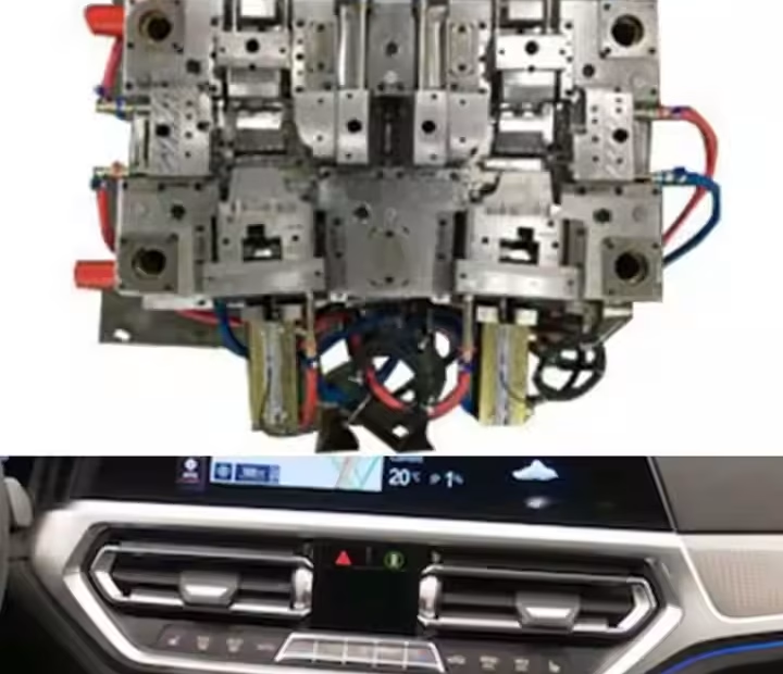
The automotive instrument panel serves as the primary interface for driver information interaction. Its complex geometry, optical transmission zones, multi-material integration, and stringent assembly tolerances impose significant engineering challenges on the molds used for its formation. The design and manufacturing quality of these molds directly determine the precision, functionality, and long-term reliability of the instrument panel assembly.
Core Functions and Technical Objectives of Instrument Panel Molds
- Accurate Geometric Replication: Faithfully reproduce design surfaces, including complex ribs, clips, locating posts, wiring channels, vent structures, and decorative textures.
- Optical Component Molding: Produce transparent or translucent plastic parts with high light transmission and stress-free surfaces for pointer windows, warning light areas, display covers, etc.
- Multi-Material Integration Capability: Support two-shot/multi-shot injection molding for rigid substrates with soft-touch surfaces (e.g., PVC, TPU), or provide precise substrates for subsequent overmolding processes.
- Dimensional Stability Assurance: Maintain micron-level tolerances under the high temperature and pressure of injection molding and subsequent environmental variations during use.
- High-Efficiency Production and Longevity: Achieve rapid cycle times and endure millions of injection cycles while retaining critical dimensions and surface quality.
Key Elements of Mold Structure Design
Mold structure forms the physical foundation for achieving the above objectives, requiring systematic solutions to the following critical aspects:
- Parting Line Design:
- Determine the main parting line based on the product’s maximum projected contour and ejection requirements.
- Address complex undercuts: Employ precision sliding cores (sliders), actuated by angled pins, hydraulics, or motors, ensuring precise and reliable movement.
- Address internal undercuts: Utilize lifters (internal sliders), performing lateral core pulling during ejection. This compact design imposes high demands on ejection system layout.
- Gating System Design:
- Gate type selection: Given the large size and complex structure of instrument panels, hot runner systems with multi-point valve gates are often employed to achieve balanced filling, reduce weld lines, improve material utilization, and shorten cycle times.
- Runner balancing: Ensure molten plastic flows uniformly and simultaneously to the end of the cavity, preventing localized over-packing or short shots.
- Cold slug well design: Effectively trap and isolate the leading cold material to prevent surface defects or gate blockage.
- Temperature Control System Design:
- Intensive cooling circuits: Position numerous cooling channels close to the cavity, core, and slider surfaces for efficient, uniform heat exchange.
- Zoned temperature control: Implement differentiated temperature management for transparent areas, thick sections, high-gloss surfaces, etc., optimizing cooling efficiency and minimizing internal stress.
- Medium selection: Utilize standard cooling water, chilled water, or oil temperature units based on required temperature control precision.
- Ejection System Design:
- Multi-point balanced layout: Combine ejector pins, ejector sleeves, and stripper plates to ensure distortion-free ejection of large thin-walled parts.
- Ejection path planning: Avoid critical features (e.g., clips, ribs) to prevent ejection marks or damage.
- Return and early-return mechanisms: Ensure the ejection system fully resets accurately before mold closing to prevent interference with sliders.
- Venting System Design:
- Adequate venting channels: Position vent slots or vent inserts at melt flow ends, parting lines, insert junctions, and around ejector pins.
- Depth control: Maintain vent slot depths typically within 0.015-0.03mm to prevent flash.
- Mold Base and Guiding System:
- High-rigidity mold base: Provide sufficient support strength and resistance to deformation.
- Precision guiding: Employ high-precision guide pillars and bushings to ensure accurate, deviation-free movement of mold halves and sliders.
Instrument Panel Molds Manufacturing Process Flow
Instrument Panel Molds manufacturing translates design intent into physical form through a series of precision machining and treatment steps:
- Rough Machining and Pre-processing:
- Mold base blank preparation: Source blanks according to design specifications.
- Datum surface machining: Establish precise machining datums.
- Preliminary cavity/core contour machining: Remove bulk material.
- Pre-drilling of structural holes, water lines, etc.
- Heat Treatment:
- Apply heat treatment to critical components to achieve required hardness, toughness, and wear resistance combinations.
- Precision Machining:
- CNC High-Speed Milling: Machine complex freeform surfaces, ribs, and fine features.
- EDM (Electrical Discharge Machining): Machine deep slots, narrow gaps, sharp corners, and hardened areas inaccessible to milling (e.g., fine textures).
- Wire EDM: Machine precision through-holes and insert profiles.
- Deep Hole Drilling: Create long-distance cooling channels.
- Grinding: Ensure dimensional accuracy and surface finish of critical mating surfaces (parting lines, slider interfaces), guide pillars, and bushings.
- Surface Treatment and Special Processes:
- Texture Etching: Apply photochemical etching to create leather grains, wood grains, geometric patterns, etc., on cavity surfaces.
- Polishing: Achieve mirror finishes (Ra ≤ 0.01μm) on transparent and high-gloss cavity areas.
- Surface Hardening: Apply treatments like PVD, CVD, TD coating, or nitriding to enhance wear and corrosion resistance on critical areas.
- Component Precision Inspection:
- Utilize CMMs (Coordinate Measuring Machines), profilometers, surface roughness testers, etc., to rigorously inspect dimensions, geometric tolerances, and surface quality of all machined features.
- Mold Assembly and Testing:
- Thorough cleaning of all components.
- Precision assembly per drawings, ensuring smooth movement of all dynamic components with specified clearances.
- Mold closing test: Verify parting line contact.
- Trial molding on injection machine: Validate filling, dimensions, appearance, ejection. Perform necessary mold modifications.
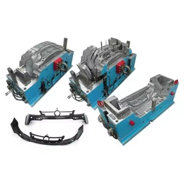
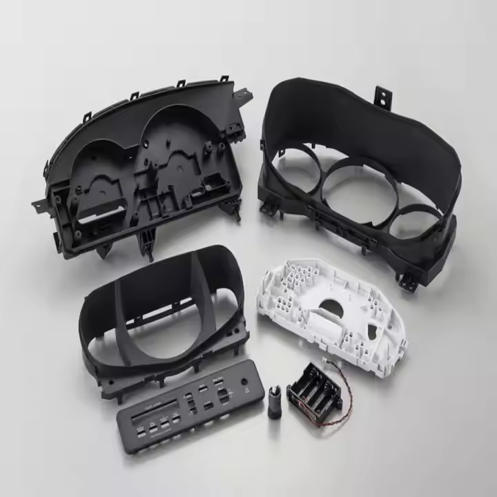
Core Dimensions of Instrument Panel Molds Quality Verification
- Dimensional Accuracy and Repeatability:
- Perform full dimensional inspection of first articles and production samples using CMMs.
- Conduct SPC (Statistical Process Control) analysis for production stability.
- Inspect critical assembly dimensions using dedicated gauges.
- Surface Quality:
- Visual inspection: Gloss uniformity, color consistency, weld lines, flow marks, silver streaks, sink marks, etc.
- Light transmission and haze testing for transparent areas.
- Comparison of textured areas against master samples.
- Structural and Functional Validation:
- Clip engagement force and retention force testing.
- Adhesive bond strength testing for appliqués.
- Optical performance testing for light-transmitting areas.
- Mold Life and Stability:
- Continuously monitor trends in critical dimensions during production.
- Periodically inspect wear on key areas: parting lines, cavity surfaces, sliders, ejector pins.
- Document mold maintenance history and cumulative shot count.
Mold Maintenance and Performance Assurance Strategies
Long-term stable operation of precision molds relies on scientific maintenance management:
- Standardized Operating Procedures: Develop and enforce standard protocols for mold installation, removal, cleaning, and lubrication.
- Preventive Maintenance Plan:
- Regular maintenance: Clean water lines, lubricate moving parts, check fastener torque, inspect cooling/heating systems.
- Key component inspection: Periodically assess wear on guide pillars/bushings, slider rails, ejector plates, return springs.
- Professional Repair and Refurbishment:
- Damage repair: Professionally restore dents, corrosion, or worn areas.
- Surface reconditioning: Repolish, re-etch textures, or repair hardened layers.
- Wear part replacement: Timely replace ejector pins, sleeves, springs, seals, etc., reaching end-of-life.
- Storage Management: For long-term storage, perform thorough cleaning, apply rust prevention, store in a dry environment, and relieve preload on critical moving components.
Automotive instrument panel molds represent complex engineering systems integrating precision mechanical design, advanced materials processing, thermal management, and rigorous quality control. Their development and manufacturing level directly reflects the core competitiveness of the automotive component supply chain. Continuous focus on structural optimization, process innovation, and full lifecycle management is fundamental to ensuring the efficient, stable, and long-term operation of this critical production asset, ultimately delivering high-quality automotive cockpit experiences to the market.
FAQ
What are the core design challenges of automotive instrument panel molds?
Simultaneously resolving complex surface forming, stress-free requirements for optical areas, multi-material compatibility, and micron-level dimensional stability.
Why are hot runner systems universally adopted in instrument panel molds?
Reduces material waste, eliminates cold runners, enables multi-point temperature control, and ensures uniform filling of large thin-walled parts.
How do instrument panel molds achieve dual-material (soft/hard) injection molding?
Through rotating mold bases or slider transfer stations with two-stage material injection, requiring ≤0.02mm positioning accuracy.
Why is venting design critical in instrument panel molds?
Gas entrapment causes burn marks/short shots; vents at melt flow ends must be 0.015-0.03mm deep.
How to solve deep rib ejection challenges in instrument panel molds?
Nitrogen-treated ejector sleeves combined with mold release agents reduce ejection resistance by ≥40%.
>>You may also like
Standards & References
The following industry standards are referenced in this article: