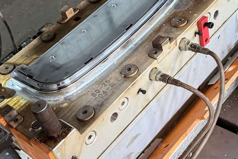
Speed bump molds, as key industrial tools for shaping modern road safety installations, embody standardization in physical form. These specially designed rigid cavity structures carry precise geometric instructions. Through the filling and solidification of rubber, plastic, and other materials, they mass-produce uniform, dimensionally accurate speed bump components. The precision of the mold directly correlates with the final physical characteristics and practical effectiveness of the speed bump on the road, serving as the invisible technical core influencing the safety function of the device.
Design Specifications for Speed Bump Molds
- Fundamental Structural Geometry
Standard speed bump molds cavity structures strictly adhere to universal specifications: their cross-section features a uniformly sloped arch profile, with a top width typically between 50 and 100 millimeters, and a standard elevation height of 50 millimeters. To meet vehicle passage requirements, molds incorporate standardized longitudinal spacing specifications. Speed bump molds designs preemptively include essential base installation holes and drainage groove features. - Critical Dimensional Parameters
- Total mold length is generally set at 1 meter or longer standard units to accommodate actual road paving width needs;
- The inclination angle of the arched surface is rigorously maintained between 12° and 14°;
- The cross-section profile of the raised portion employs a smooth transition curve devoid of sharp edges, ensuring the molded product meets engineering requirements for smooth vehicle traversal.
- Material Selection Principles
Speed bump molds must withstand immense mechanical stress during high-temperature, high-pressure molding. Material selection is based on fulfilling the following criteria:- High Strength: The material possesses high resistance to deformation under elevated temperatures;
- High Wear Resistance: Suitability for long-term, high-frequency repetitive actions inherent in production cycles;
- Corrosion Resistance: Ability to withstand chemical substances generated during rubber vulcanization;
- Thermal Stability: Ensuring dimensional stability and precision against deformation at high temperatures;
- Primary material options include various grades of steel alloys (commonly hardened tool steel), engineered alloys. Some lightweight molds also explore the use of reinforced polymer composites.
- Mechanical Strength Requirements
The mold structure must possess significant rigidity. The material’s yield strength must substantially exceed the pressure impact loads during injection or compression phases to prevent cavity distortion or structural warping. The thickness design of the main mold body requires sufficient strength redundancy beyond accommodating the cavity space, guaranteeing reliable dimensional precision without drift over prolonged operation. - Standardization and Operability Considerations
Mold design integrates practical operability factors for production environments: incorporating detachable features to facilitate demolding from complex geometries; designing installation guides and locating components to ensure precise positioning; providing venting channels to allow escape of trapped air during rubber injection/compression; incorporating precise temperature control channels to enhance vulcanization efficiency.
Speed bump molds Manufacturing Technical Regulations
- Basic Mold Forming Processes
Primarily employs casting and machining processes:- Casting Method: Pouring molten metal into preformed sand or investment shells to create the fundamental mold body structure upon cooling;
- Machining: Utilizing CNC milling, turning, or grinding equipment to process solid metal blocks into high-precision parts.
Both methods require subsequent finishing operations to achieve the final required dimensions and surface quality.
- Structure Enhancing Heat Treatment Techniques
Most mold steels require heat treatment to enhance durability. Principal processes:- Quenching: Heating the steel component above its critical temperature point followed by rapid cooling to substantially increase hardness;
- Tempering: Reheating the quenched part to a specific temperature and holding it, then cooling to optimize toughness and reduce internal stresses.
The heat treatment cycle must strictly follow the specific thermal profile prescribed for the alloy grade.
- Precision Machining Sequence
Post-heat treatment, the mold undergoes fine machining to achieve the final geometric tolerances. High-precision CNC equipment ensures adherence to technical specifications. Contoured surfaces are often produced using ball-nose cutters for accurate profiling. Critical mating surfaces undergo grinding and polishing to reduce friction coefficients. - Quality Inspection Protocol
Finished molds must undergo multiple inspection stages:- Full dimensional verification using Coordinate Measuring Machines (CMM);
- Surface hardness testing via Rockwell or Brinell hardness testers to confirm conformity with material specifications;
- Visual and optical surface inspection for defects, cracks, or excessive tooling marks;
- Non-destructive testing (NDT) like ultrasonic testing for large or critical molds to detect internal flaws like inclusions or voids.
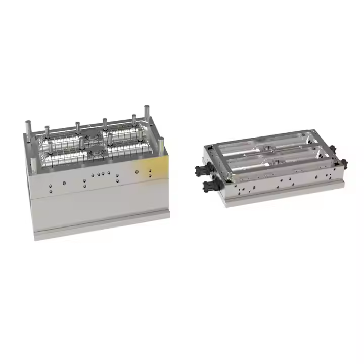
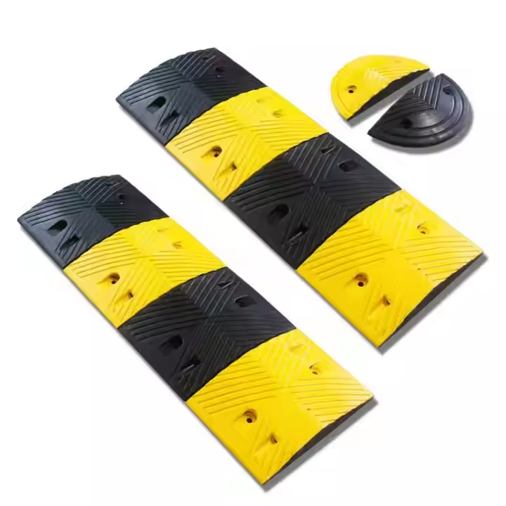
Manufacturing Process of Speed bump molds
Speed bump molds manufacturing integrates precision machining and heat treatment:
- Rough Machining:
- Material preparation (forgings preferred over rolled stock for denser structure).
- Milling/planing six surfaces to establish reference planes.
- Drilling large holes, pre-machining cavity profiles, leaving adequate finish machining allowance.
- Heat Treatment:
- Pre-hardened steel: Generally requires no further heat treatment.
- Steel requiring hardening: Undergoes quenching and tempering to target hardness, relieving stresses.
- Precision Machining:
- CNC Milling: Machines complex contours, parting surfaces, hole patterns. Utilizes rigid machines and tooling.
- Electrical Discharge Machining (EDM): Processes deep slots, sharp corners, fine textures, or areas inaccessible to milling. Commonly employs cavity sinking EDM and wire EDM.
- Deep Hole Drilling: Creates long cooling channels.
- Turning/Grinding: Machines guide pins, bushings, ejector pins, etc.
- Finishing and Assembly:
- Benchwork: Fitting parting surfaces, polishing cavities, assembling inserts, installing ejection mechanisms.
- Assembly: Mounting mold plates, installing guide systems, connecting temperature control lines, debugging ejection/return mechanisms.
- Surface Treatment: Nitriding, coating, or plating as required.
- Trial Molding and Acceptance:
- Mounting and debugging on respective presses/injection molding machines.
- Trial production to verify product dimensional accuracy, surface quality, demolding smoothness, and flash control.
- Optimizing process parameters (temperature, pressure, time).
- Measuring critical mold dimensions and motion accuracy for design compliance.
Speed bump molds Application Operation Procedures
- Rubber Speed Bump Production Sequence
- Pre-mixed and compounded rubber material is cut to sizes matching the mold cavity;
- Raw rubber is fed into the mold cavity mounted within high-temperature vulcanization equipment;
- The mold is closed and subjected to high pressure (approximately 150 kgf/cm²), simultaneously heated to between 130°C and 170°C to initiate vulcanization;
- Pressure and temperature are maintained for the set cure time to complete crosslinking;
- Pressure is released, the mold opens, and the cured speed bump product is ejected;
- After cooling, flash removal (definishing) is performed.
- Plastic Speed Bump Production Sequence
- Thermoplastic material (e.g., HDPE, Nylon) is heated and melted using extrusion or injection molding units;
- The hot melt is injected or extruded into the precisely machined mold cavity;
- The material is cooled and solidified before mold opening to retrieve the part;
- Additional components may be assembled to form the complete speed bump structure.
- Demolding Quality Control Requirements
The demolding process requires stringent control to prevent product damage:- Continuous application of release agents (typically silicone-based) onto mold interior walls to ensure easy separation;
- Allowance for sufficient cooling-induced part shrinkage before disassembly; forceful stripping is prohibited;
- Periodic inspection of release agent coverage integrity on high-friction areas.
- Equipment Maintenance Standards
Essential for sustained production stability and mold lifespan:- Implementation of a regular lubrication schedule for moving parts and guide rails;
- Periodic inspection of clamping bolts and fasteners to prevent structural loosening;
- Prompt cleaning of residual rubber fragments to avoid jamming or surface damage;
- Immediate repair of critical surface scuffs, scratches, or wear spots;
- Proper rust protection and storage in controlled environments for idle molds.
Conclusion
Speed bump molds represent complex engineering products integrating materials science, precision mechanical design, advanced manufacturing, and heat treatment technologies. Their core value lies in providing a reliable forming solution for the large-scale, efficient, high-quality production of speed bumps meeting stringent road safety standards. By precisely replicating design geometries, withstanding high-pressure, high-temperature cyclic loads, enabling efficient temperature control, and ensuring smooth demolding, molds directly determine the dimensional accuracy, structural integrity, surface quality, and long-term performance of speed bumps.
Continuous innovations in materials, design optimization (especially CAE and AM), advanced machining, and intelligent monitoring are steadily enhancing the performance, lifespan, and production efficiency of speed bump molds, reducing unit costs. These advancements simultaneously provide the foundational support for developing more complex, durable, and environmentally friendly road safety installations. Ultimately, progress in mold technology serves the core objective of enhancing road traffic safety.
FAQ
What is the core function of a speed bump molds?
Provide a rigid cavity with specific geometric shape to form standardized speed bump components through filling, pressurization, and solidification of fluid or semi-fluid materials.
Why do speed bump molds require heat treatment?
Heat treatment (quenching + tempering) enhances surface hardness and overall toughness of steel molds, increasing resistance to high-pressure forming stresses and extending service life.
What precision machining equipment is commonly used in speed bump molds manufacturing?
Computer numerical control (CNC) milling machines, lathes, electrical discharge machining (EDM) units, supplemented by grinding and polishing operations for micron-level tolerance control.
Can a speed bump molds be compatible with different raw material formulations?
Accommodate same material type (rubber/plastic). Evaluate flow characteristics and shrinkage rate differences when switching formulations; adjust temperature/pressure parameters as needed.
>>You may also like
Standards & References
The following industry standards are referenced in this article: